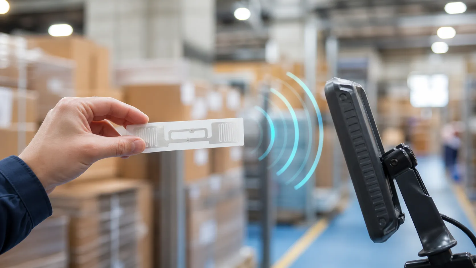
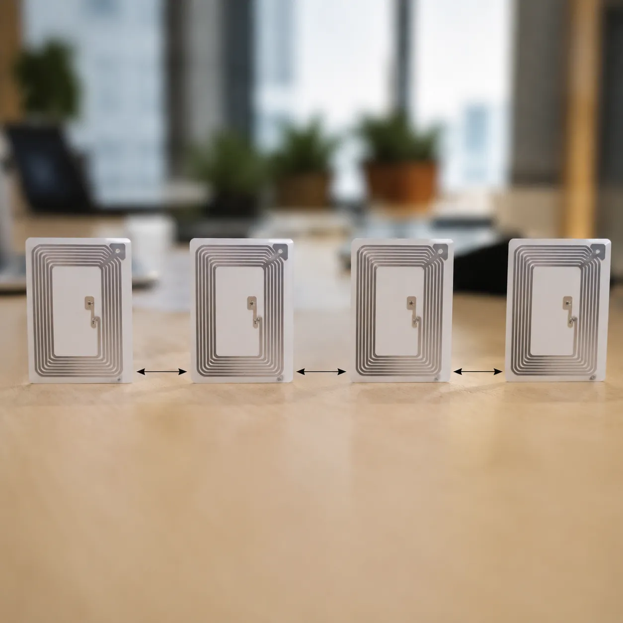
What is the minimum distance between uhf rfid tags to avoid interference? In free air at 860-960 MHz, plan for 1 to 2 inches (2.5 to 5 cm) between passive rfid tags—more when metal, moisture, or high reader power compress the safe zone. Below we cover mutual coupling and detuning, spacing tables by application, anti-collision protocol limits versus physical detuning, and OEM hardware for high multi-tag reading density.
Why UHF RFID Tag-to-Tag Interference Occurs — Coupling and Detuning
When you pack passive RFID tags too close together, their read rates drop. In the 860-960 MHz frequency band, Ultra-High Frequency (UHF) tags rely on capturing electromagnetic energy from an interrogator antenna. When tags crowd each other, they stop acting as isolated transponders and start distorting the local RF field.
To maintain an optimal detection range, understanding the physical disruptions caused by tight rfid tag-to-tag proximity is essential.
The Physics of Mutual Coupling
When two passive RFID tags are placed side by side, their antennas share a magnetic and electric field. This interaction is called mutual coupling. Instead of independently drawing power from the reader, the adjacent antennas begin to transfer energy between themselves. This parasitic relationship alters the electrical characteristics of both tags, severely degrading the overall multi-tag reading density.
The Phenomenon of Tag Detuning
Every UHF tag is finely tuned to resonate at a specific frequency. Mutual coupling triggers mutual coupling detuning, which shifts the tag's resonant frequency away from the standard 860-960 MHz range.
- Impedance Mismatch: The antenna's impedance no longer matches the silicon chip.
- Power Loss: The tag fails to wake up because it cannot collect enough RF energy.
- Reduced Read Range: Even if the tag responds, its signal attenuation prevents the reader from capturing the data.
Tag Collision vs. Signal Reflection
It is important to distinguish between hardware interference and data collision:
| Interference Type | Cause | Impact on System |
|---|---|---|
| Signal Reflection & Detuning | Physical proximity and altered antenna impedance. | The tag becomes blind to the reader's energy. |
| Tag Collision | Multiple tags talking back at the exact same millisecond. | Managed by the reader's software anti-collision protocol. |
While software handles data collisions, no firmware can fix a tag that cannot wake up due to physical signal reflection and detuning.
Environmental Accelerators
The minimum distance between uhf rfid tags to avoid interference isn't dictated by the tags alone. Everyday environmental factors can compress the safe passive rfid tag spacing boundary:
- High Moisture Levels: Water absorbs UHF energy, compounding signal loss.
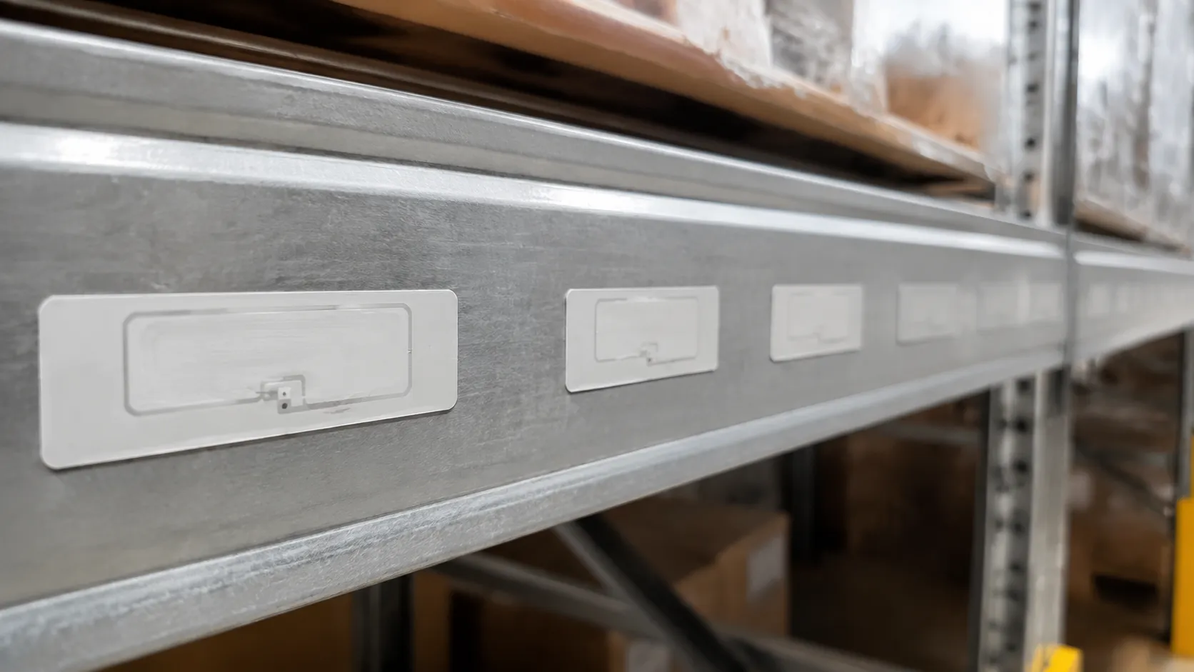
- Metal Surfaces: Placing tags near metal causes severe reflections, requiring specialized on-metal rfid isolation tactics.
- Reader Power Settings: High reader power expands the interrogator antenna field, which can worsen the coupling effect among tightly packed tags.
Minimum Distance Between UHF RFID Tags to Avoid Interference
Standard Rule of Thumb for Free Space
When deploying passive RFID tags in standard, open-air environments, we generally recommend a minimum spacing of 1 to 2 inches (2.5 to 5 cm) between tags. In the 860-960 MHz frequency band, maintaining this basic physical gap ensures that the interrogator antenna field can read each item cleanly without performance drops.
The Near-Field Boundary Restriction
If your asset tracking setup forces tags closer together, you hit the near-field boundary. When passive tags sit within 0.5 inches (1.2 cm) of each other, they enter a zone where electromagnetic interference spikes sharply. This close proximity shifts the antenna tuning, which drastically cuts down your overall detection range and causes missed reads in high multi-tag reading density environments.
Special Application Guidelines
Different tracking environments require specific adjustments to your uhf rfid tag minimum spacing guidelines to keep your system accurate:
| Application Surface | Recommended Minimum Spacing | Deployment Insight |
|---|---|---|
| Standard Retail & Apparel | 1 to 1.5 inches (2.5 to 3.8 cm) | Keeps tag-to-tag proximity safe for hanging garments. |
| Corrugated Cartons / Pallets | 2 inches (5 cm) | Maintains consistent tag orientation alignment on master cases. |
| On-Metal RFID Isolation | 1.5 inches (3.8 cm) | Requires anti-metal tags to combat both metal reflection and tag crowding. |
| Vehicle Access Control | 4 to 6 inches (10 to 15 cm) | Prevents overlapping signals under high reader power optimization settings. |

Engineering Solutions to Mitigate Interference in High-Density Environments
When you are stacking assets or inventory closely together, keeping the minimum distance between uhf rfid tags to avoid interference becomes a balancing act. If your application demands tight packing, standard system setups will fail without intentional intervention. We utilize specific hardware configurations and protocol tweaks to maintain a reliable detection range and stable multi-tag reading density, even when tags are tightly clustered.
Leveraging Anti-Collision Protocols
Modern passive rfid systems rely heavily on built-in anti-collision algorithms like the Class 1 Gen 2 slotted Aloha protocol. This protocol forces tags to respond in randomized time slots rather than all at once.
- How it helps: It prevents data packets from overlapping in the air.
- The limitation: While it stops data collisions at the reader level, it cannot fix physical mutual coupling detuning if the tags are physically touching or too close.
Deploying Dense Reader Mode (DRM)
In high-density US warehousing or logistics hubs, multiple readers often operate simultaneously in the 860-960 MHz frequency band. This creates massive electromagnetic interference.
- Channel Separation: DRM forces the interrogator antenna to shift its transmit channels and use specific spectral masks.
- Noise Reduction: This isolates the reader's signal from neighboring noise, preventing the reader from overpowering the faint responses of closely spaced tags.
Optimizing Tag Orientation Alignment
Physical layout can change how radio waves interact. Correct tag orientation alignment is one of the easiest ways to bypass the strict limits of your uhf rfid tag minimum spacing guidelines.
| Tag Alignment Strategy | Impact on Interference | Best Use Case |
|---|---|---|
| Parallel Matching | High risk of mutual coupling if spaced below 2 cm. | Standard palletized goods with consistent spacing. |
| 96-Degree Offset | Drastically reduces cross-talk and detuning. | High-density bins and stacked small items. |
| Linear vs. Circular | Circular reader antennas tolerate mixed orientation better. | Vehicle access control and automated conveyor belts. |

Transitioning to Specialized Near-Field UHF Hardware
When your application requires a near-zero passive rfid tag spacing—such as tracking pharmaceutical vials or small jewelry items—traditional far-field antennas will fail. You must switch to specialized near field hardware.
Near-field UHF antennas utilize magnetic loops rather than electric fields. This strictly confines the energy to a tight near field boundary, allowing you to read tags packed tightly together without accidentally triggering adjacent items or suffering from severe signal attenuation.
Advanced OEM/ODM Tag Engineering: How JN RFID Solves Proximity Challenges
When managing a high-density deployment within the 860-960 MHz frequency band, standard off-the-shelf tags often fall short. At JN RFID, we engineer specialized solutions that redefine the minimum distance between uhf rfid tags to avoid interference. We eliminate the guesswork of passive rfid tag spacing by building interference resistance directly into the hardware.
Custom Antenna Substrate Profiling
We design custom antenna layouts specifically to fight mutual coupling detuning. By altering the geometric footprint and substrate materials, our engineers minimize the interrogator antenna field distortion when tags are stacked close together. This profiling maintains a stable impedance, allowing high multi-tag reading density without dropping performance.
Premium Silicon Integration
Our tags integrate advanced, high-sensitivity silicon chips featuring integrated anti-collision protocol optimizations.
- Enhanced Chip Sensitivity: Requires less turn-on power from the interrogator antenna.
- Interference Mitigation: Maintains a reliable detection range even when subjected to severe electromagnetic interference.
- Power Efficiency: Maximizes the available reader power to ensure rapid responses in crowded zones.
100% Pre-Shipment Read/Write QA Validation
| Test Parameter | Validation Metric | Target Outcome |
|---|---|---|
| Read Range Stability | Near-field boundary testing | Zero blind spots in tight spacing |
| Write Threshold | Power ramp validation | Consistent encoding at high density |
| Orientation Tolerance | Multi-angle rotation checks | Reliable tag orientation alignment |
The JN RFID Engineering Lifecycle
Our engineering lifecycle analyzes your specific tag placement restrictions, environment, and vehicle access control or logistics requirements. We then customize the signal attenuation and shielding properties of our tags, delivering an optimized uhf rfid tag to tag minimum spacing solution that guarantees flawless data capture.