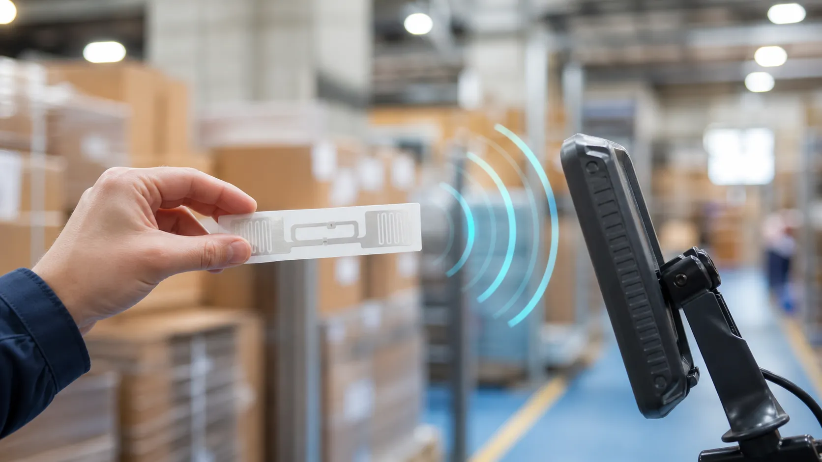
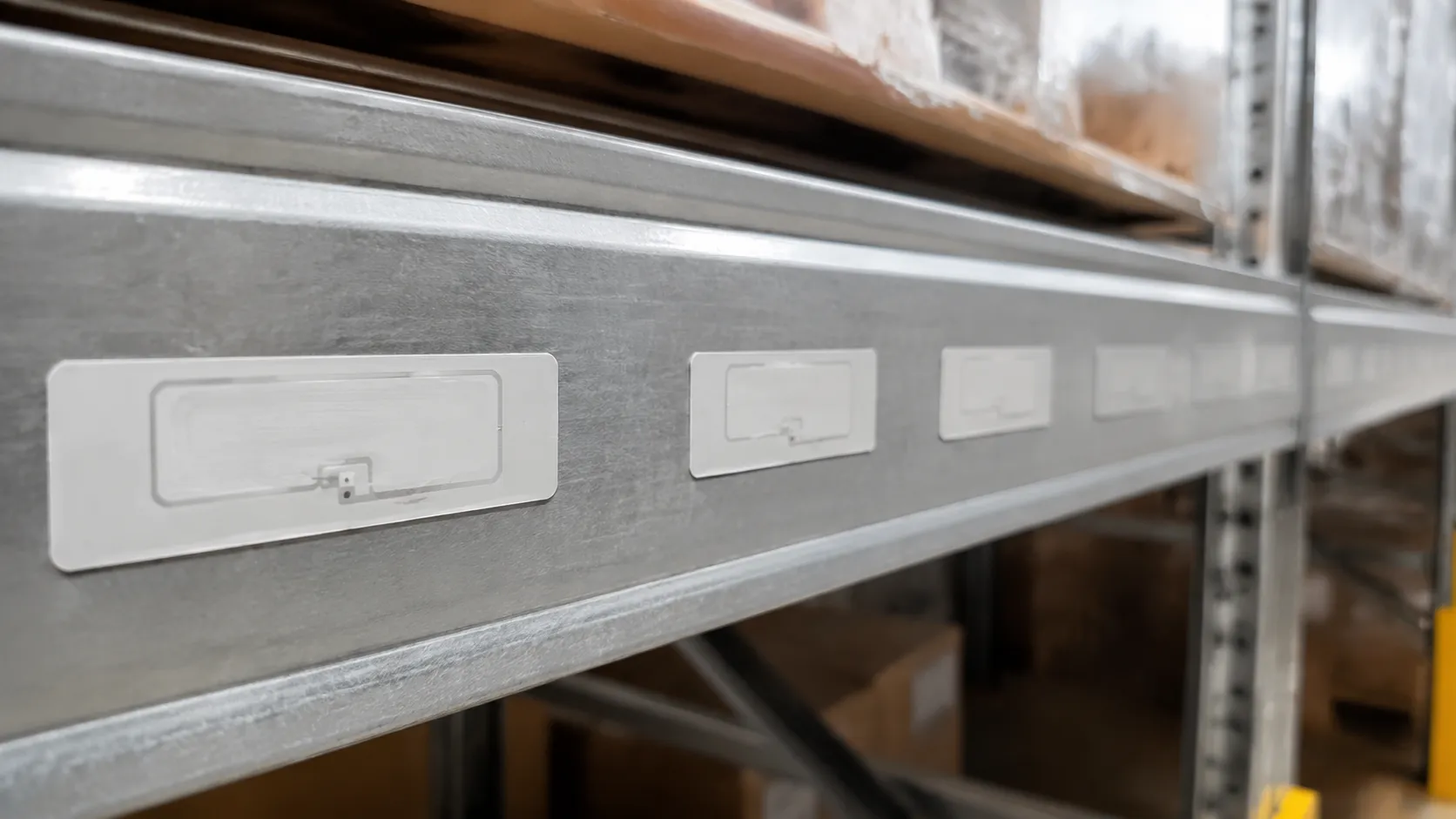
0.5 英寸(12.7 毫米)是金属上超高频 RFID 标签最小间距的物理红线——低于此间隙,标签会进入彼此的反应近场,读取范围会迅速缩小。
- 首先出现故障的是: 互耦导致天线失谐;集成电路始终无法获得足够的功率进行响应。
- 金属会使情况更糟: 金属表面会反射射频信号,从而压缩安全间隙,使其小于自由空气布局。
- 设计标准:需要使用带有介电间隔或铁氧体背衬的专用金属标签——标准标签在钢材上无法正常工作。
金属上超高频RFID标签的最小间距
0.5英寸近场红线
对于 UHF 无源 RFID 标签,0.5 英寸(12.7 毫米)是绝对的物理“红线”。
当金属基板上两个标签之间的距离小于0.5英寸时,它们会进入彼此的反应近场区。这种近距离接触会立即引发相互耦合和严重的电磁干扰。
- 天线失谐:相邻标签的存在会改变天线的电长度。
- 阻抗不匹配:标签的阻抗偏离了微芯片的设计特性,导致芯片无法唤醒。
- 读取范围崩溃:这种严重的失谐可能会使您的操作读取范围从几米降至几厘米,或者使标签完全无法读取。
基质和环境影响
金属表面会起到电磁反射器的作用,这自然会扭曲射频场。然而,金属的具体成分以及周围环境会影响安全距离的范围,使其缩小或扩大:
- 黑色金属与有色金属:铜和铝等高导电性金属会产生更强烈的涡流,因此对间距最小值的要求比钢更严格。
- 液体邻近效应:液体会吸收超高频能量。如果您的金属设备含有液体或与液体相邻,则标签间距过小会加剧失谐效应。
- 安装深度:将标签齐平安装或直接嵌入铣削的金属槽中会集中射频能量,因此与使用凸起的金属标签相比,必须留出更大的安全间隙。
主参考间距矩阵
为确保部署过程中避免相互耦合和干扰,请遵循以下基本安装指南:
| 资产/应用程序类型 | 建议最小间距 | 主要射频风险 | 最佳实践设计 |
|---|---|---|---|
| 重工业金属资产 | 2.0 英寸(50.8 毫米) | Severe detuning & reflection | Use dedicated on-metal labels with thick dielectric spacing layers. |
| Retail Metal Hardware | 1.0 in (25.4 mm) | Signal shadowing & shielding | Space tags evenly; avoid stacking metal items directly on top of each other. |
| Corrugated Cartons (with Metal Content) | 1.5 in (38.1 mm) | Attenuation & detuning | Stagger tag placement vertically to break linear coupling paths. |
| Liquid-Filled Metal Containers | 3.0 in (76.2 mm) | RF absorption & detuning | Maximize distance; position tags on the dryest, flat surfaces of the container. |
| Vehicle Windshields (Metal-Oxide Glass) | 2.0 in (50.8 mm) | Parasitic coupling | Keep tags away from metallic window pillars and windshield wiper elements. |
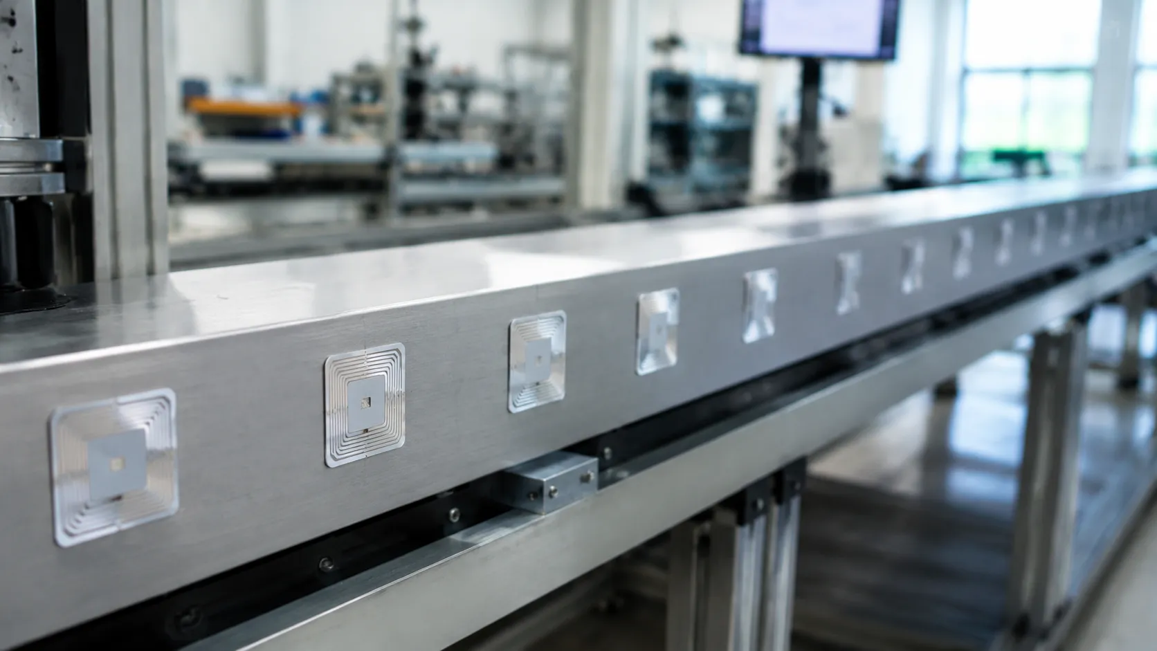
UHF RFID on Metal: Anti-Collision vs Physical Detuning
Teams often hope a quick software setting or a boost in reader configuration can fix read issues in tight spaces. The hard truth is that digital adjustments cannot rewrite the laws of physics. If you ignore the minimum spacing for UHF RFID tags on metal, the resulting physical interference will completely block your hardware from communicating.
EPC Gen2 Anti-Collision vs. Antenna Detuning
A common misconception is that standard reader protocols can resolve spacing issues. They cannot. Here is why:
- How anti-collision works: The EPC Gen2 protocol uses a "Q-algorithm" to manage signals when hundreds of tags try to talk to a reader at the same time. It acts like a traffic cop directing a crowd of people who are all shouting.
- The reality of detuning: When passive RFID tags are placed too close together on metallic surfaces, they experience severe antenna detuning. The metal absorbs and reflects the RF energy, preventing the tag's integrated circuit (IC) from receiving enough power to turn on.
- The result: An unpowered tag cannot shout. No matter how advanced the reader's anti-collision software is, it cannot organize a conversation with a tag that is physically "dead" due to lack of signal resonance.
Dense Reader Mode (DRM) Limitations
Some engineers attempt to use Dense Reader Mode (DRM) to resolve crowded tag environments, but this conflates two entirely different RF challenges.
| Feature | Dense Reader Mode (DRM) | Proper Tag Spacing |
|---|---|---|
| Primary Target | Reader-to-reader interference | Tag-to-tag mutual coupling |
| How it Works | Spreads out reader channels to stop noise | Maintains physical distance to protect tag antennas |
| Impact on Metal | Does not restore a detuned tag's read range | Prevents metal from shorting out the tag's signal |
Compare minimum spacing between UHF RFID tags for the 3.0 in on-metal baseline. DRM is designed to keep multiple RFID readers from drowning each other out in a busy warehouse. It does absolutely nothing to stop the physical, localized electromagnetic interference that occurs when tags are crammed together on a metal asset. If the physical layout is wrong, your read range will drop to zero, regardless of how clean your reader transmission is.
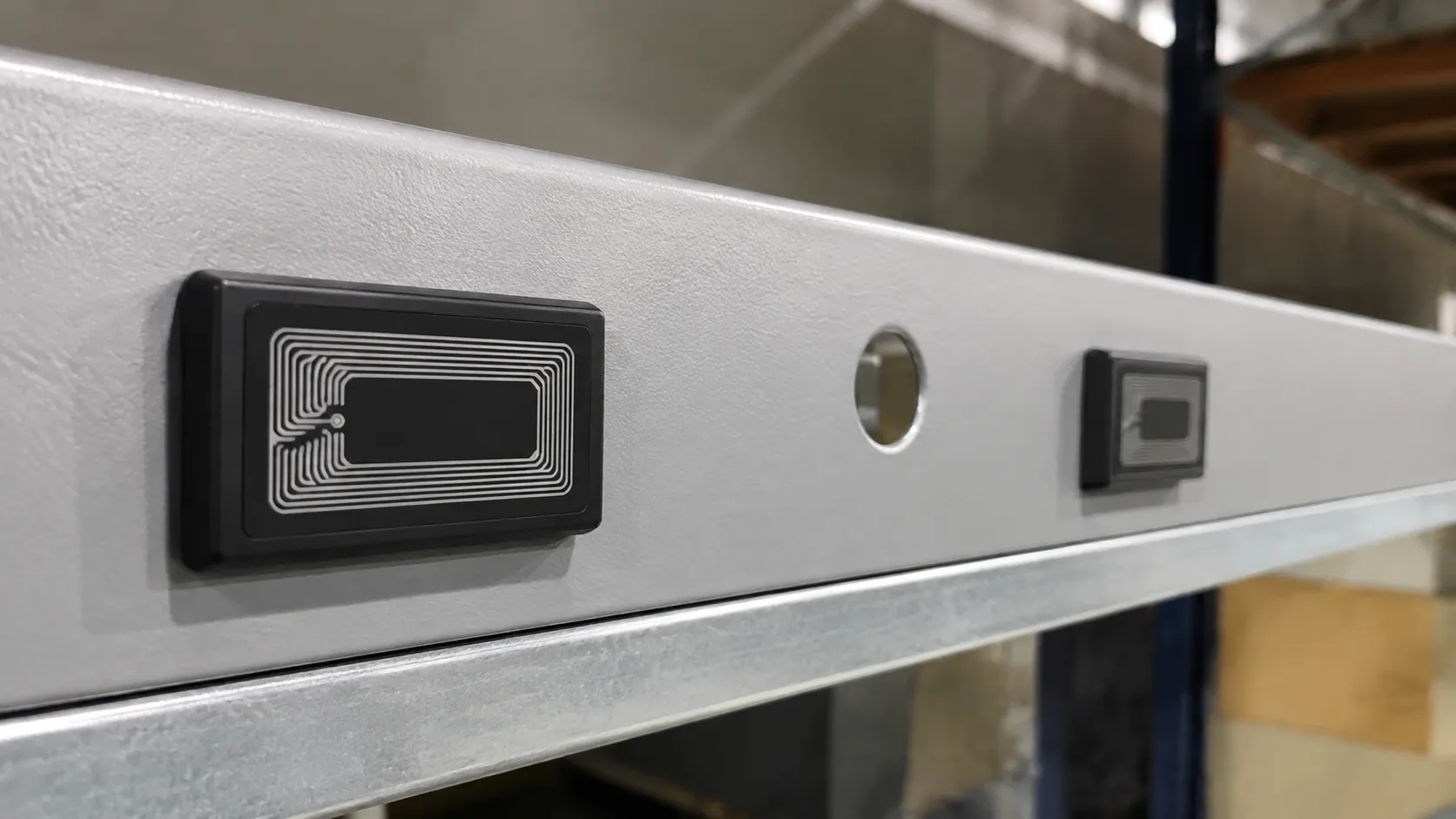
On-Metal Tag Design: Dielectric Spacing & Ferrite Backing
On metallic surfaces, standard tags fail—on-metal UHF RFID tags isolate the antenna from the substrate. To maintain a reliable read range and prevent severe electromagnetic interference, we design specialized hardware that physically isolates the antenna from the metal.
Dielectric Spacing and Ferrite Backing
To prevent immediate antenna detuning, a physical barrier must exist between the tag's antenna and the metal surface.
- Spacer thickness: A precise dielectric spacing layer lifts the antenna off the metal. Engineers target roughly quarter wavelength (λ/4) at UHF, allowing the reflected wave to reinforce the incoming signal rather than cancel it out.
- Ferrite backing: For ultra-thin builds, a ferrite layer redirects RF energy, shielding the antenna and preserving frequency tuning when clearance is minimal.
Designing Resilient On-Metal Labels
Specialized on-metal inlays manipulate magnetic paths so signal resonance stays stable.
| Tag Type | Backing Material | Core Benefit | Common Use Case |
|---|---|---|---|
| Ceramic Tags | Hard Ceramic | Extremely durable; high dielectric constant supports a smaller tag size with strong read range. | Tool tracking, heavy machinery |
| Encapsulated Foam Tags | Specialized Thick Foam | Flexible and impact-tolerant while maintaining required spacer thickness. | Curved metal containers, IT assets |
Placement Strategies to Reduce Minimum Spacing
When uhf rfid tag minimum spacing on metal is pushed to physical limits, standard linear placement will fail due to mutual coupling. We recommend using physical orientation to bypass this bottleneck:
- 90-Degree Angular Offsets: Rotating adjacent tags 90 degrees relative to each other rotates their polarization fields, drastically reducing signal interference between closely grouped assets.
- 45-Degree Offsets: If a perfect grid is required, angling the tags at 45 degrees breaks the direct linear coupling path, allowing you to mount tags closer together without losing signal resonance.
- 交错垂直放置:垂直交错放置标签以打破线性耦合——请参阅标签安装指南,以便在曲面资产上保持一致的放置。
金属标签间距:现场验证清单
即使规划周全,实际仓库和工厂的物理环境也会发生变化。金属表面超高频RFID标签的最小间距应通过现场验证确定,而非仅凭纸上谈兵的假设。
使用这份简明易懂的检查清单来测试您的标签密度,并保护您的读取范围免受意外下降的影响。
逐步台架验证
在将无源RFID标签批量安装到金属表面之前,应先对样品进行台式测试,以检测失谐并找到最佳物理位置。使用圆极化读取器天线以获得可重复的基线读取结果。
- 建立基准:将单个金属标签安装到资产上。在目标读卡器功率下测量其最大读取范围。
- 添加第二个标签:将第二个标签放置在第一个标签旁边,间距与您计划的最小间距相同。
- 测量性能下降:再次检查读取范围。如果读取距离下降超过 10%,则说明相互耦合导致标签失谐。您需要增大间距。
- 识别射频“盲区”:将贴有标签的物品靠近金属角、支架或弯折处。金属边缘会使射频场发生扭曲,形成盲区,导致标签突然无法读取。调整安装指南,使标签与任何金属边缘保持至少 1 英寸的距离。
功率因数:平衡读取器发射功率(dBm)
功率并非总是解决问题的办法。当标签紧密地贴在金属部件上时,将读卡器的发射功率调得过高反而会导致读取失败。
| 读卡器功率(dBm) | 对间距较小的标签的影响 | 建议采取的措施 |
|---|---|---|
| 高功率(30+ dBm) | 压制射频场,导致邻近标签出现严重干扰和错误读取。 | 在密集追踪区域应避免使用。 |
| 优化功率(20–27 dBm) | 仅激活天线正前方的目标标签,减少能量溢出。 | 最佳设置。使用能够提供可靠读数的最低功率设置。 |
| 低功率(<20 dBm) | 不会发生耦合,但可能无法为具有较厚介电层或铁氧体背衬的标签供电。 | 仅限近距离手持扫描使用。 |
为了确保系统流畅运行,请在读卡器上找到能够保持 100% 读取率的最低功率(瓦特或 dBm)设置。这样可以缩小射频辐射范围,防止标签之间相互干扰,并确保频率调谐始终保持高度精确。