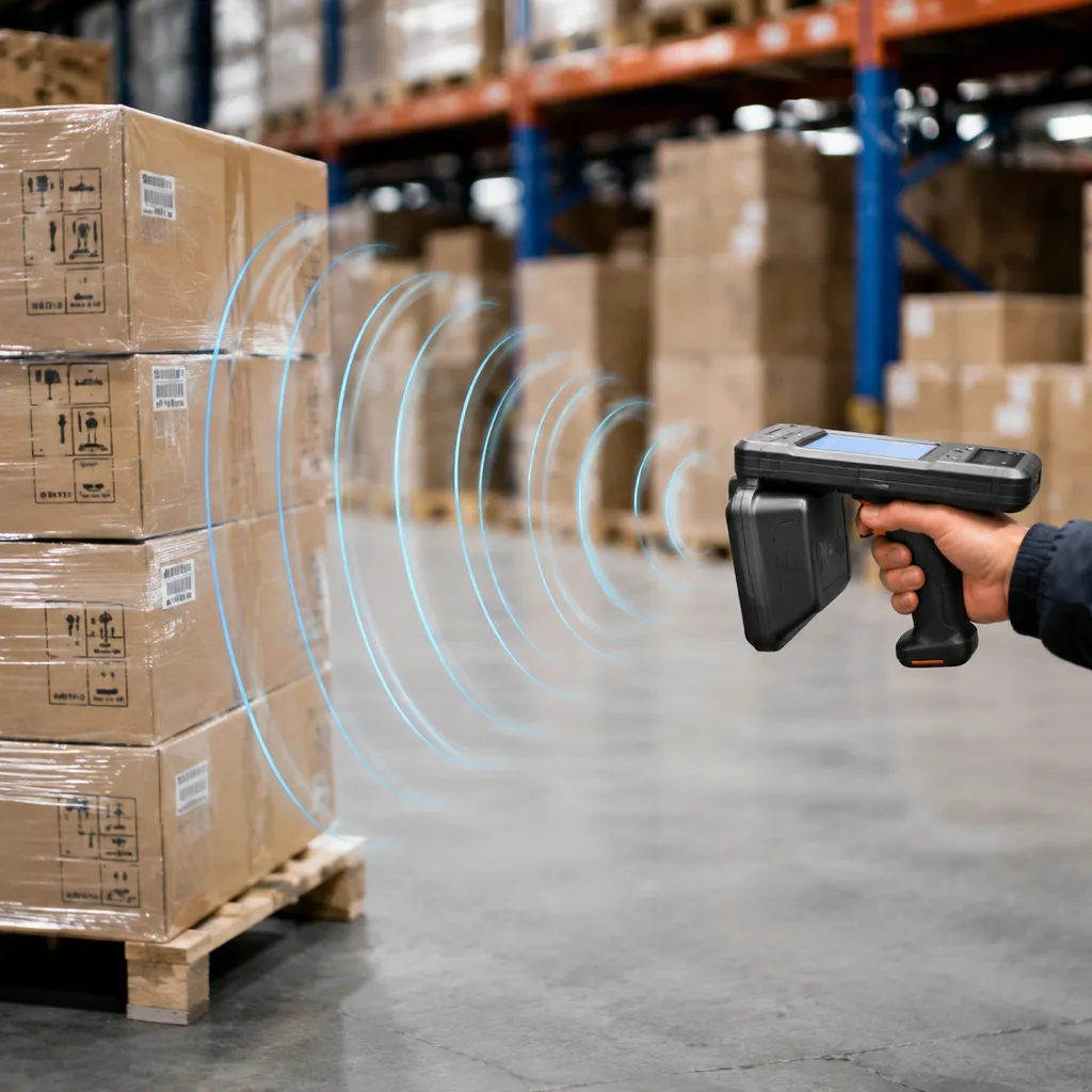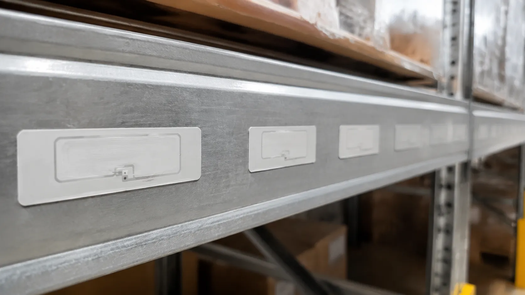
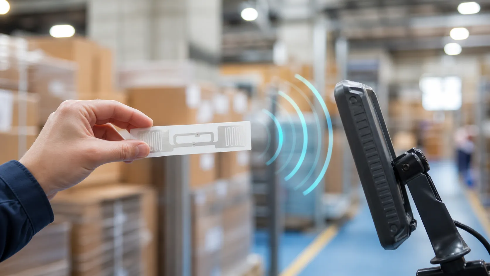
Choosing the correct uhf rfid tag frequency starts with deployment distance and regional spectrum—not silicon brand alone.
| Primary need | Recommended band |
|---|---|
| Long-range dock-door inventory management & supply chain logistics | UHF 860–960 MHz (RAIN RFID / passive rfid) |
| Tap-to-pay / item-level NFC | High frequency 13.56 MHz |
| Access control through liquids | Low frequency 125–134 kHz |
| Battery-powered beacons & long-range ping | Active rfid (onboard power, separate reader pairing) |
Realized read range still depends on regional sub-bands (902-928 MHz FCC vs 865-868 MHz ETSI), rfid reader power, and rfid antenna gain.
UHF RFID Tag Frequency: The 860–960 MHz Operating Window
In RF engineering, the Ultra-High Frequency (UHF) band occupies the electromagnetic spectrum from 300 MHz to 3 GHz. For RFID applications, international governing bodies have allocated a dedicated operating window within this range.
- Standardized Operating Window: Passive rfid UHF tags operate within the 860–960 MHz band[1].
- Global Standard: Regulated globally under the ISO/IEC 18000-6C standard and commercially certified via the RAIN RFID protocol[1].
- Primary Propagation Method: Uses far-field radiative coupling, where tag antennas capture electromagnetic energy from the reader and transmit data back via RF backscatter.
LF vs HF vs UHF RFID Tag Frequency Comparison
Selecting the right uhf rfid tag frequency requires balancing read range, scan speed, and environmental tolerance. Compare passive rfid UHF against active rfid platforms when battery-powered beacons are in scope:
| Feature | Low Frequency (LF) | High Frequency (HF) | Ultra-High Frequency (UHF) |
|---|---|---|---|
| Frequency Range | 125–134 kHz | 13.56 MHz | 860–960 MHz |
| Coupling Mechanism | Near-field Inductive | Near-field Inductive | Far-field Radiative |
| Typical Read Range | < 10 cm (< 4 in) | Up to 1 m (3 ft) | 5 to 12+ m (16 to 40+ ft) |
| Data Transfer Speed | Low | Moderate | High (Bulk Scanning) |
| Liquid/Metal Resistance | High | Moderate | Requires Specialized Design |
| Key Applications | Access control, livestock | NFC payments, library items | Supply chain, logistics, asset tracking |
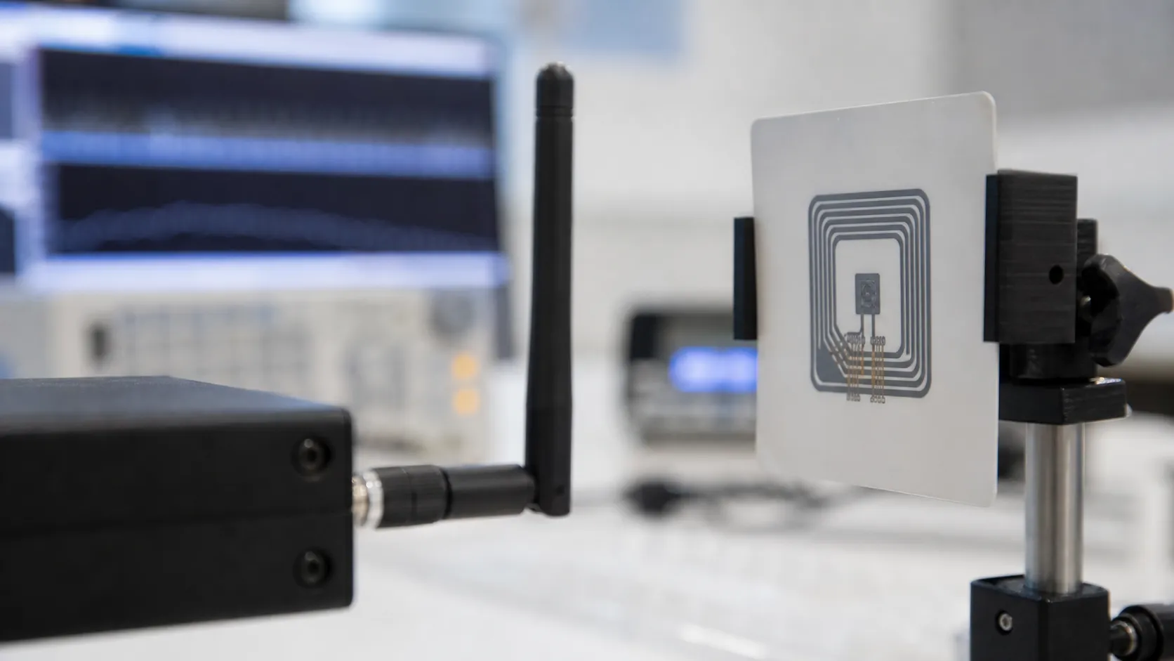
Key Frequency Band Characteristics
- Low Frequency (125–134 kHz): Operates via magnetic induction. Offers short read distances but easily penetrates water, liquids, and biological tissue.
- High Frequency (13.56 MHz): Enables tap-to-pay and NFC compatibility. Works well for single-item identification with moderate data rates.
- Ultra-High Frequency (860–960 MHz): Designed for high-speed, long-range deployments. Enables pass-through inventory readers to perform batch scans of hundreds of tags per second.
Regional UHF RFID Frequency Allocations and Compliance
When deploying RFID hardware across borders, regional frequency regulations dictate your tag's read range, transmission power, and hardware design. While the overall uhf rfid tag frequency band spans 860-960 MHz, local telecom authorities restrict which exact channels your system can use.
FCC 902-928 MHz: North American Operating Standards
In the US, Canada, and Mexico, the FCC governs the 902–928 MHz band. This allocation gives engineering teams substantial bandwidth and power advantages:
- Maximum Radiated Power: Allows up to 4 Watts EIRP (Effective Isotropic Radiated Power), delivering maximum passive tag read distances.
- Frequency Hopping Spread Spectrum (FHSS): Requires the rfid reader to continuously hop across 50 channels under FCC Part 15 rules[2], preventing signal congestion in dense warehouse settings.
ETSI Regulations: European Frequency Limits
European deployments under ETSI historically operated on tighter spectrum boundaries with lower output thresholds:
- Legacy ETSI Band (865–868 MHz): Capped at 2 Watts ERP (3.28W EIRP) using Listen-Before-Talk (LBT) protocols, requiring the reader to scan for clear channels before transmitting.
- Upper ETSI Band (915–921 MHz): Recent ETSI EN 302 208 updates unlocked higher power limits (up to 4W EIRP) and wider channels, significantly improving European read rates for high-speed supply chain logistics.
Global Spectrum Map: Asia-Pacific and Beyond
Outside North America and Europe, local regulatory agencies enforce distinct sub-bands within the broader 860-960 MHz window.
| Region / Country | Governing Body | Frequency Band | Max Power Limit | Key Protocol Feature |
|---|---|---|---|---|
| North America | FCC | 902–928 MHz[2] | 4W EIRP | FHSS channel hopping |
| Europe (Lower) | ETSI | 865–868 MHz[3] | 2W ERP | LBT (Listen-Before-Talk) |
| Europe (Upper) | ETSI | 915–921 MHz | 4W EIRP | High-power channels |
| Japan | TELEC | 916.8–923.4 MHz | 4W EIRP | Strict channel spacing |
| China | SRRC | 920–925 MHz | 2W ERP | Fixed channel assignment |
| Australia / NZ | ACMA / RSM | 920–926 MHz | 4W EIRP | Frequency hopping |
Wideband RFID Inlay Design for Global Supply Chains
Cross-border freight creates a core RF challenge: a tag tuned strictly for FCC 902-928 MHz loses read sensitivity when passing through an ETSI 865-868 MHz reader gate.
Wideband RFID inlay and broadband dipole antenna designs maintain low return loss across the entire 860-960 MHz spectrum for reliable backscatter at international ports, warehouses, and distribution hubs.
RF Physics: How UHF RFID Tag Frequency Governs Performance

Far-Field Radiative Coupling and Backscatter Communication
Unlike LF and HF systems that rely on near-field magnetic induction, the uhf rfid tag frequency range (860–960 MHz) operates primarily via far-field coupling. The reader antenna projects electromagnetic energy through the air. When these RF waves reach a passive UHF RFID tag, the tag’s dipole antenna harvests the radiation, converts it into direct current, and powers up the integrated circuit.
Once powered, the chip rapidly toggles its antenna impedance. This alters the reflection coefficient of the incoming wave, bouncing a modified signal back to the receiver. This process—known as backscatter communication—transmits the tag's EPC data across long distances without an onboard power source.
Key Factors Determining Read Range
The physics of propagation in the 860-960 MHz band enable passive read distances between 5 to 12+ meters (16 to 40 feet). Three core variables calibrate these distances in real-world deployments:
- Reader Transmit Power: Radiated output (up to 4W EIRP in FCC regions) directly dictates how far the powering field reaches.
- Antenna Gain: High-gain directional rfid antenna layouts focus RF energy into tight beams to maximize line-of-sight distance.
- Path Loss Management: RF signal strength drops rapidly as distance increases. Matching tag sensitivity with custom antenna geometries ensures the chip wakes up under low incident power levels.
Anti-Collision Algorithms for High-Speed Batch Scanning
High-density supply chain environments demand instant read capabilities across massive tag populations. Operating under the EPC Class 1 Gen 2 / RAIN RFID air interface[1], UHF readers manage data throughput using Slotted Aloha anti-collision algorithms.
- Dynamic Time Slots: The reader instructs tags to respond randomly within a specific set of time slots, automatically adjusting slot counts based on tag density.
- Signal De-confliction: Prevents response overlap when hundreds of tagged assets enter the read zone at once.
- High Throughput: Allows pass-through portal systems to process up to 1,000 tags per second on fast-moving warehouse conveyors and dock doors.
Managing RF Attenuation and Detuning in UHF RFID Systems
Operating in the 860–960 MHz range offers incredible speed and range, but environmental factors directly impact performance. Liquids and metals interact heavily with the UHF RFID tag frequency band. As a direct hardware manufacturer, we design tag architectures specifically engineered to overcome signal absorption, reflection, and multi-tag interference in harsh deployment environments.
The Liquid and Moisture Challenge: Dielectric Signal Attenuation
Water and high-moisture items are primary absorbers of RF energy in the 860–960 MHz spectrum. When UHF energy hits liquid, the water molecules convert the RF power into low-level thermal energy, causing severe dielectric signal attenuation.
- The Problem: Liquids absorb the reader's signal, preventing passive chips from powering up, while choking off the backscatter communication returning to the reader.
- Mounting Standoffs: Specialized 2 mm to 5 mm foam spacers or rigid mounting brackets physically separate the tag inlay from wet surfaces.
- Wideband Antenna Tuning: Wideband inlay layouts maintain functional resonance even when moisture shifts the operating center frequency.
The Metallic Surface Challenge: On-Metal Tag Detuning
Mounting a standard inlay directly onto conductive surfaces like steel, aluminum, or copper causes immediate performance failure—see on-metal UHF tags for hardened layouts. Metal reflects RF waves, creating destructive phase cancellation and severe on-metal tag detuning that shorts out standard dipole antennas.
| Hardened Solution | Construction | Primary Deployment Use Case |
|---|---|---|
| Encapsulated Ceramic Tags | High-dielectric ceramic substrate with integrated microstrip antenna | Tool tracking, small metal assets, high-temperature industrial processing |
| Ground Plane Isolation Tags | Ferrite or specialized synthetic spacer backing between antenna and adhesive | Metal shipping containers, returnable transport items (RTIs), machinery |
| Flexible On-Metal Labels | Ultra-thin printable labels with an integrated RF shielding layer | IT asset management, server racks, metal inventory boxes |
Preventing Tag Shadowing and Mutual Coupling
When tags are packed tightly together on pallets, retail racks, or bin inventory, their proximity distorts the surrounding RF field. This leads to mutual coupling failures and signal shadowing, where outer tags physically block inner tags from receiving power.
- Maintain Minimum Spacing: Keep a minimum 10 mm to 15 mm physical gap between parallel tags to prevent tag-to-tag RF loading.
- Antenna Pattern Optimization: Dual-dipole and omnidirectional inlay designs improve multi-axis energy absorption, minimizing dead spots in dense inventory stacks.
- Staggered Placement: Offset tag placements on adjacent cartons to prevent direct overlapping of tag antennas.
UHF RFID Tag Architecture and Silicon Integration
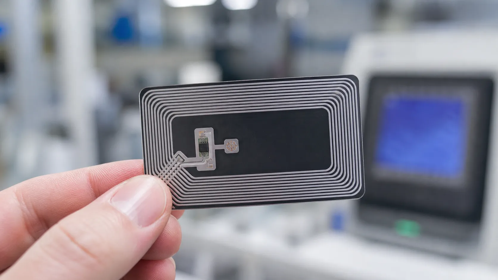
Protocol Standards: EPC Class 1 Gen 2 and ISO/IEC 18000-6C
Every tag complies with EPC Class 1 Gen 2 and ISO/IEC 18000-6C standards. These protocols govern how readers and passive tags exchange data across the 860-960 MHz UHF RFID tag frequency band. Adhering to these global benchmarks guarantees interoperability across compliant Gen2 UHF RFID tags and fixed or handheld rfid reader hardware worldwide[1].
Memory Bank Structure: Reserved, EPC, TID, and User
Passive UHF chips divide their non-volatile silicon memory into four distinct logical banks. Choosing the right layout depends on how much data your system needs to store directly on the tag:
- Reserved Memory: Holds 32-bit Access and Kill passwords. This section allows field technicians to lock memory banks against unauthorized writes or permanently decommission retired tags.
- EPC Memory: Stores the Electronic Product Code (typically 96-bit to 496-bit). This is the primary payload read during rapid pass-through inventory scans.
- TID Memory: Contains a factory-locked, unalterable Tag Identifier assigned at the silicon foundry. It includes the manufacturer code and a unique chip serial number, serving as the ultimate anti-counterfeiting safeguard.
- User Memory: Provides writable storage ranging from 0 bits up to 8KB. High-capacity user memory chips let you log maintenance histories, calibration metrics, and serial data directly on the asset without requiring constant cloud connectivity.
Silicon Selection: Impinj Monza vs. Alien Higgs Performance
The integrated circuit (IC) defines read sensitivity, range performance, and data retention under harsh operating conditions. Authentic silicon from leading manufacturers matches specific operational demands.
| Silicon Platform | Core Models | Reader Sensitivity | Memory Configuration | Ideal Application |
|---|---|---|---|---|
| Impinj® Monza / M700 | Monza R6-P, M730, M750 | Down to -24 dBm | Up to 128-bit EPC, Auto-tuning features | High-speed retail, apparel, and high-density logistics |
| Alien® Higgs | Higgs-3, Higgs-4, Higgs-9 | Down to -22.5 dBm | Up to 512-bit EPC, 512-bit User memory | Enterprise asset tracking, industrial manufacturing |
| High-Memory Silicon | Fujitsu FRAM, NXP UCODE | Standard sensitivity | Up to 8KB high-write endurance memory | Aerospace maintenance, automotive assembly logging |
Higher reader sensitivity (expressed in lower negative dBm values) allows the chip to activate with less RF energy, extending total read distance across the UHF RFID tags frequency spectrum. For severe industrial deployments, industrial IC packaging ensures reliable data retention across extreme thermal windows spanning -40°F to +185°F (-40°C to +85°C).
Customizing UHF RFID Tag Form Factors
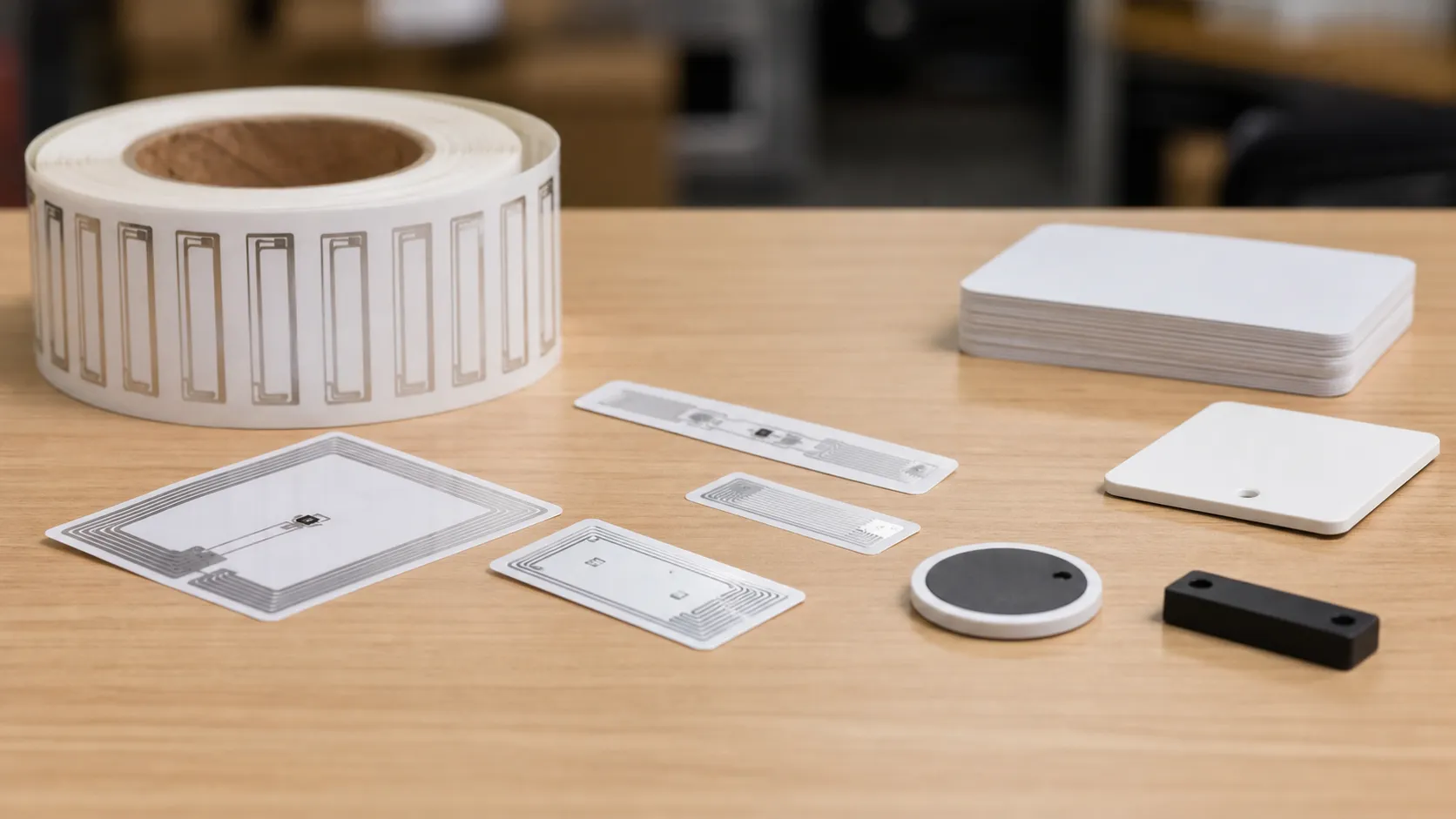
Matching target uhf rfid tag frequency (860–960 MHz) with the proper physical enclosure is critical for reliable performance. Antenna performance changes near metal, liquids, or high heat. Tailored form factors built to survive specific physical environments while maintaining optimal RF read rates.
Flexible Smart Labels and Inlays
For high-volume supply chain logistics, corrugated box tracking, and retail item tagging, flexible labels are the standard.
- Dry Inlays: Clear PET substrate housing the microchip and etched aluminum antenna. Designed for label converters.
- Wet Inlays: Adhesive-backed inlays supplied on rolls, ready for direct application to non-conductive surfaces.
- Paper and PET Smart Labels: Thermal-transfer printable face sheets compatible with standard RFID barcode printers. Ideal for shipping cartons and pallet tracking across global supply chains.
Hardened Industrial Enclosures
Standard labels fail under heavy physical impact, chemical exposure, or extreme temperatures. Rugged hard tags protect the microchip and preserve antenna tuning in harsh operational settings.
| Form Factor | Housing Material | Key Specifications | Primary Deployments |
|---|---|---|---|
| Ceramic Tags | Encapsulated Ceramic | High heat tolerance (up to 200°C), ultra-compact | Tool tracking, small metal assets |
| Flexible Laundry Tags | Vulcanized Rubber / Silicone | IP68 rated, withstands 200+ industrial wash cycles | Commercial linen, uniform rentals |
| Rugged IP68 Tags | Impact ABS / Polycarbonate | UV-proof, waterproof, high-impact resistance | Heavy equipment, outdoor yard assets |
Dual-Frequency Options (HF + UHF)
Combining multiple frequency bands onto a single tag bridges enterprise logistics with end-user interactions. Hybrid dual-frequency inlays integrate both Ultra-High Frequency (860–960 MHz RAIN RFID) and High Frequency (13.56 MHz NFC) into a single silicon footprint.
- UHF Logistics Performance: Enables fast, long-range bulk scanning at warehouse dock doors and distribution hubs.
- HF/NFC Smartphone Compatibility: Allows field technicians or consumers to tap the exact same tag with a standard smartphone for instant product authentication or manual maintenance logging.
Factory-Direct UHF RFID Tag Frequency Tuning and Manufacturing
Precision Antenna Etching and Wideband Tuning
Custom aluminum and copper dipole antennas tune to targeted uhf rfid tag frequency—whether North America (902–928 MHz FCC)[2], Europe (865–868 MHz ETSI)[3], or global wideband (860–960 MHz)—including 860–960 MHz wideband inlays for cross-border freight.
Automated Inline Quality Assurance
A dead tag on an automated line stops production. At JN RFID, every roll and inlay batch undergoes 100% automated inline electronic testing. We write, read, and verify every integrated circuit (IC) at operational power thresholds during manufacturing to guarantee zero-defect field deployments for high-volume logistics.
Direct Factory Customization Specs
We build tailored form factors to fit your exact operational environment and system encoding rules:
| Customization Option | Manufacturing Capability | Target Benefit |
|---|---|---|
| Frequency Tuning | Custom dipole designs for FCC, ETSI, or global 860–960 MHz | Maximize read range on metal, liquid, or cardboard |
| Surface Printing | Full-color CMYK offset, variable QR codes, and 1D/2D barcodes | Instant visual identification and optical scanning backup |
| Silicon Encoding | Pre-programmed EPC memory, locked TID, and custom user memory | Plug-and-play integration with your existing WMS/ERP |
| Adhesive Backing | 3M industrial acrylic, heavy-duty foam, and high-temp adhesives | Secure attachment to low-surface-energy plastics and metal |
Certified Direct-Factory Supply Chain
Factory-direct manufacturing under ISO 9001:2015, CE, FCC, and RoHS-certified processes ensures authentic silicon integration and reliable uhf rfid tag frequency performance across antenna layout and chip selection.
Frequently Asked Questions About UHF RFID Tag Frequency
What is the standard frequency range for UHF RFID tags?
The global UHF RFID tag frequency spectrum operates between 860 MHz and 960 MHz. This spectrum uses far-field backscatter communication to deliver high-speed batch scans and long-range tracking. Because individual countries regulate radio spectrums differently, wideband RFID inlays cover this entire band for seamless asset tracking and supply chain logistics rollouts.
How do regional regulations impact UHF RFID frequency?
Different regions assign distinct sub-bands and power limits within the global 860-960 MHz band. These differences affect reader output power, channel hopping, and read speed:
| Regulatory Region | Frequency Band | Max Radiated Power | Key Spectrum Protocol |
|---|---|---|---|
| North America (FCC) | 902–928 MHz | 4W EIRP | Frequency Hopping Spread Spectrum (FHSS) |
| Europe (ETSI) | 865–868 MHz / 915–921 MHz | 2W ERP | Listen-Before-Talk (LBT) |
| Asia-Pacific (China/Japan) | 916.8–925 MHz | Varies by country | Regional channels & bandwidth caps |
How do liquid and metal affect UHF RFID tag performance?
Water and metal alter the electromagnetic field around a passive RFID tag:
- Liquids: Cause dielectric signal attenuation, absorbing RF energy in the 860–960 MHz range and killing the tag's read distance.
- Metals: Cause on-metal tag detuning by reflecting RF energy and shorting out standard dipole antennas.
High-density foam spacers, ceramic substrates, and specialized ground planes isolate the antenna from conductive surfaces.
What is the typical read range for UHF RFID tags?
Standard passive UHF tags offer a read range between 5 to 12+ meters (16 to 40+ feet). Actual performance depends on three core hardware factors:
- Antenna Gain: High-gain reader antennas concentrate RF energy farther.
- Transmit Power: Readers operating under FCC 902-928 MHz specs push up to 4W EIRP for maximum reach.
- Tag Design: Larger dipole antenna layouts capture more backscatter energy than compact asset labels.
What is the difference between RAIN RFID and standard UHF RFID?
RAIN RFID is the commercial alliance term for passive UHF RFID technology that complies with the EPC Class 1 Gen 2 and ISO/IEC 18000-6C standards. While "UHF RFID" refers broadly to any RFID system operating between 300 MHz and 3 GHz, RAIN RFID specifically defines standardized 860-960 MHz inventory management systems designed for global interoperability.