What drives uhf rfid tag antenna gain in a passive UHF label? Efficient energy harvesting from the reader beam—not on-tag amplification. Below we cover dipoles and meander geometries, complex impedance matching, miniaturization techniques, circular polarization losses, and factory QA for consistent read range.
What is UHF RFID Tag Antenna Gain?
When we talk about UHF RFID tag antenna gain, we are discussing how efficiently a passive antenna captures radio frequency (RF) energy from a reader and directs it to the tag’s integrated circuit (IC). Because passive tags do not have a battery, they rely entirely on energy harvesting from the reader's signal to wake up and transmit data. Antenna gain isn't about creating power; it is about focusing it.
UHF RFID Tag Antenna Gain: Energy Harvesting Basics
A passive antenna must gather enough ambient RF energy to hit the turn-on voltage of the integrated circuit (IC). Higher signal strength through optimized gain means the tag can harvest energy from greater distances, directly increasing the overall read range. If the antenna gain is poorly tuned, the chip remains asleep, rendering the tag unreadable.
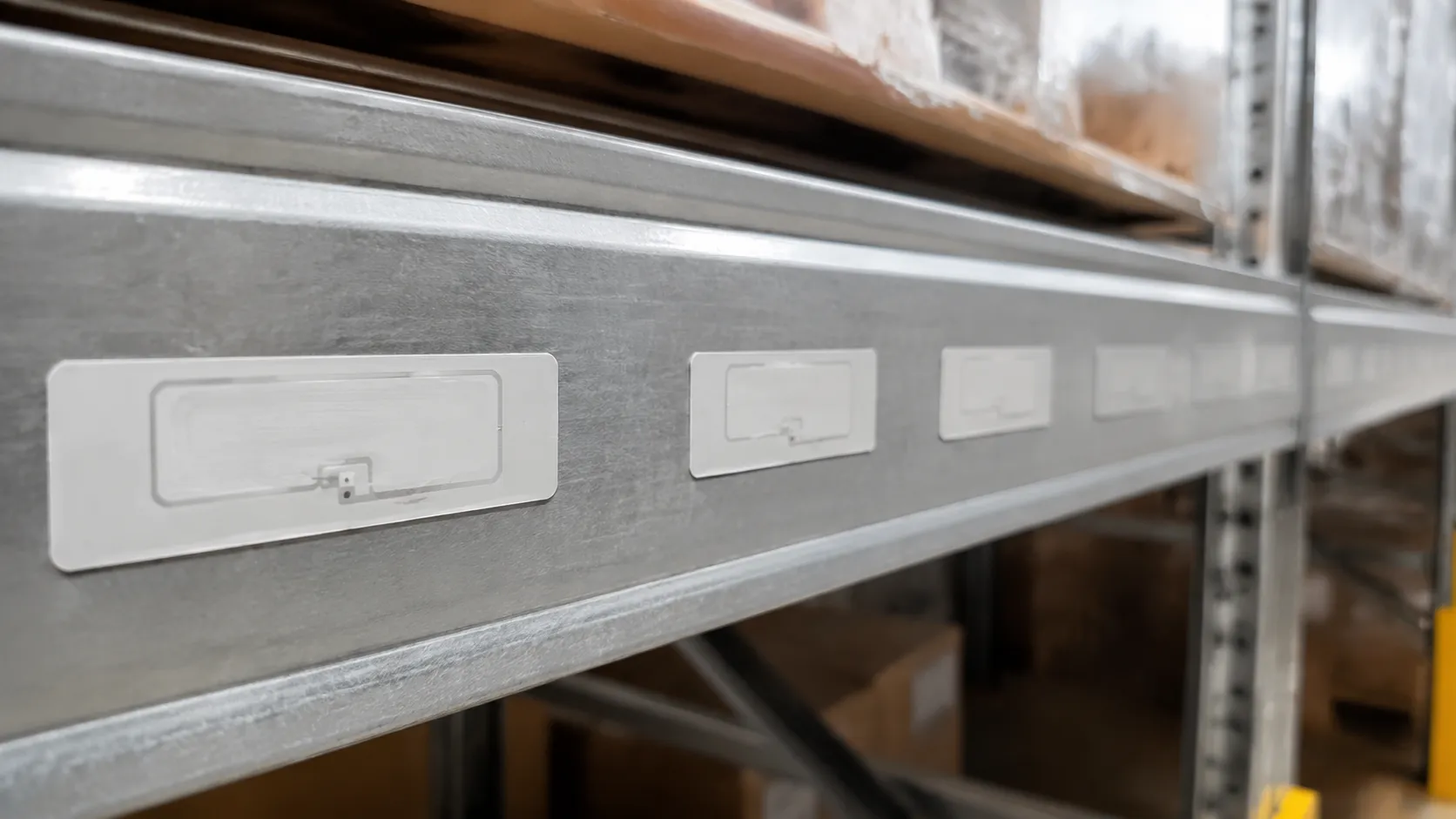
UHF RFID Tag Antenna Gain on Metal & Liquids
- Metal Surfaces: Reflect RF signals, causing phase cancellation and detuning the antenna.
- Liquids: Absorb UHF energy completely, killing the transmission distance.
- Dense Packaging: Shifts the resonant frequency away from the intended UHF band.
Without specialized tuning, a generic tag's radiation pattern distorts, drastically shrinking the detection range.
UHF RFID Tag Antenna Gain: Impedance & Geometry Tuning
We solve these environmental challenges by balancing complex antenna physics with precise physical production.
| Production Focus | Impact on Performance |
|---|---|
| Impedance Matching | Achieves perfect complex impedance alignment between the chip and the antenna to prevent signal loss. |
| Material Permittivity Control | Adjusts the layout based on whether the tag is placed on plastic, wood, or glass. |
| Geometric Tuning | Customizes dipoles and meander lines to optimize the Effective Isotropic Radiated Power (EIRP). |
By engineering the uhf rfid tag antenna gain around your specific application, we deliver reliable, high-yield tracking even in the harshest industrial environments.
The Core Physics: How UHF RFID Tag Antenna Gain Influences Your Read Range
When we design tags in our facility, uhf rfid tag antenna gain is the main lever we pull to scale your transmission distance. A passive antenna doesn't create energy, but it focuses it. By optimizing the tag gain, we directly increase the signal strength reaching the chip, allowing the tag to wake up and talk back to the reader from much farther away.
The Gain vs. Beamwidth Trade-off
Increasing your uhf rfid tag antenna gain changes the tag's radiation pattern.
- High-Gain Directional Tags: These focus energy like a flashlight. They offer maximum detection range but require the tag to face the reader panel antenna directly.
- Lower-Gain Omni-Directional Layouts: These act more like an open lightbulb. The transmission distance drops, but the tag can be read from almost any angle.
Alignment and Polarization Losses
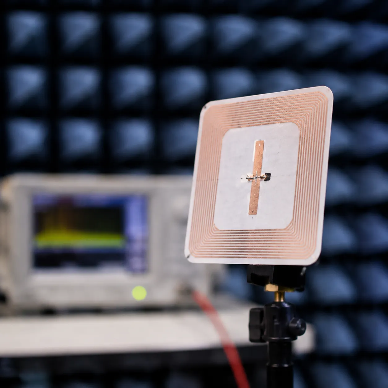
To maintain strong signal strength, the tag dipoles must align with the reader's signal. If your warehouse uses circular polarization panel antenna readers, the reader waves rotate. A standard linear tag will experience a fixed 3 dB signal loss because of this mismatch.
We combat this in production by engineering specialized loop and dual-linear geometries to ensure your assets hit peak read range regardless of how they pass through the choke point.
Technical Variables That Determine UHF RFID Tag Antenna Gain
When we design and manufacture RFID layouts, we do not just look at a generic blueprint. Achieving the optimal uhf rfid tag antenna gain requires balancing highly specific physical and material variables. A minor shift in any of these factors can completely alter the signal strength and read range.
Here is exactly what determines the performance of our tag antennas:
1. Complex Impedance Matching
Unlike traditional antennas, a passive antenna connects directly to an integrated circuit (IC). To maximize energy harvesting and power transmission, the antenna’s input impedance must be a perfect complex conjugate match to the chip's impedance. If the impedance is mismatched, signal reflections cause massive power loss, severely shrinking your detection range.
2. Antenna Form Factors and Geometries
We use various geometric layouts to manipulate the wavelength and fit tight physical constraints without losing radiation efficiency.
- Meander Line Dipoles: Bending the antenna wires into a zig-zag pattern reduces the overall uhf rfid tag size while maintaining the electrical length needed for proper resonance.
- T-Match Networks: A secondary loop structure used to tune the complex impedance and match highly capacitive RFID chips.
- Inductive Loops: These handle the magnetic coupling near the chip, fine-tuning the radiation pattern.
| Antenna Geometry | Primary Benefit | Best Common Use Case |
|---|---|---|
| Meander Line Dipoles | Drastically reduces overall tag size | Standard corrugated box tracking, apparel hang tags |
| T-Match Structures | Offers precise complex impedance tuning | High-performance supply chain and logistics tagging |
| Inductive Loops | Excellent near-field tuning capabilities | Metal-mount tags and specialized industrial environments |

3. Substrate Materials and Permittivity
The material supporting the conductive ink or copper arrays alters how the RF signal travels. Every substrate has a specific dielectric constant (permittivity) that shifts the resonant frequency.
PET Films: Highly stable, standard thin films offering predictable performance.
Conductive Inks vs. Etched Copper: Etched copper arrays offer lower resistance and higher gain consistency, while conductive inks provide cost-effective flexibility.
4. Environmental Detuning Factors
An antenna does not operate in a vacuum. When a tag is placed near high-permittivity materials (like liquids) or highly reflective surfaces (like metal sheets), the environment changes the antenna's capacitance. We engineer custom profiles to counteract these detuning effects, ensuring the uhf rfid tag antenna gain remains stable even in harsh industrial settings.
UHF RFID Tag Antenna Gain vs Miniaturization
The Developer's Challenge: Shrinking the UHF RFID Tag Size
We constantly face the demand for a smaller uhf rfid tag size. Local businesses want discreet tracking, but shrinking the physical footprint without destroying radiation efficiency is a massive hurdle. When you reduce the size of a passive antenna, you directly limit its ability to capture and radiate energy.
The Real Cost of Tag Miniaturization
Reducing an antenna's dimensions alters its natural radiation pattern and inevitably lowers the uhf rfid tag antenna gain.
- Dropped Signal Strength: Smaller antennas capture less effective isotropic radiated power (EIRP) from the reader, reducing overall signal strength.
- Impedance Shifts: Shorter lengths distort the complex impedance, making it harder to achieve an ideal match with the integrated circuit (IC).
- Reduced Read Range: A drop in gain means a direct drop in the overall detection range and transmission distance.
| Design Factor | Standard Dipole Tag | Miniaturized Tag | Impact on Performance |
|---|---|---|---|
| Footprint Size | Large (Optimized to wavelength) | Compact / Ultra-small | Fits tight spaces, but sacrifices natural resonance |
| Antenna Gain | High (Optimal) | Low to Negative dBi | Weakens the energy harvesting capability of the chip |
| Read Range | Maximum distance | Restricted distance | Requires higher reader power to compensate |
Advanced Geometries to Maintain Surface Current
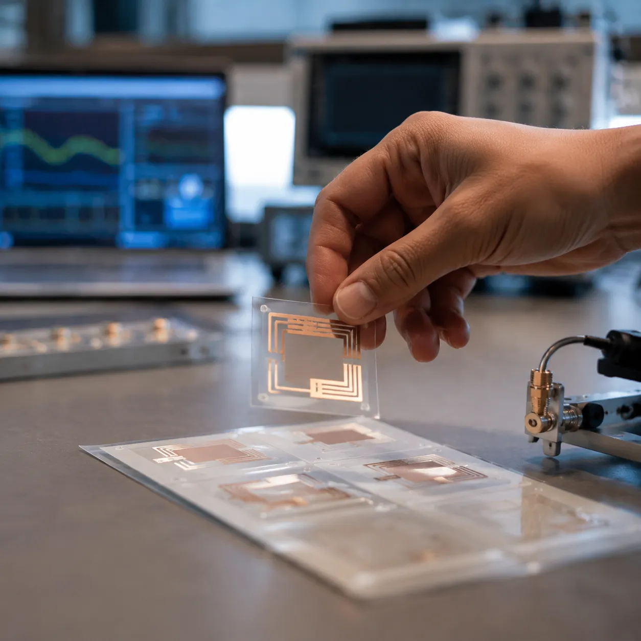
To fight back against these losses, we employ advanced geometric solutions. Instead of standard meander line dipoles, we design complex fractal layouts and 3D folding structures. These techniques wrap longer conductive paths into a smaller physical area. This maximizes the surface current and optimizes the return loss without expanding the tag dimensions, keeping your small-scale asset tracking reliable.
The Direct Factory Advantage: Custom OEM/ODM Antenna Engineering
When you look at a standard UHF RFID tag datasheet, the listed read range and signal strength usually look perfect. But in the real world, those off-the-shelf specs often fall flat. Standard tags are tested in perfect laboratory conditions. Once you place them on real-world assets like metal pallets, liquid containers, or dense packaging, the UHF RFID tag antenna gain drops dramatically.
We design and build custom OEM/ODM solutions to bridge this gap. We bypass generic layouts to optimize the passive antenna geometry specifically for your operational environment.
High-Precision Inlay Manufacturing
To maintain stable UHF RFID tag antenna gain across millions of units, mass production requires extreme physical accuracy. We utilize advanced, high-speed ultrasonic copper wire-embedding arrays and high-precision flip-chip assembly. This guarantees that every single integrated circuit (IC) bonds perfectly to the custom antenna, preventing the physical shifting that ruins signal strength and detection accuracy.
| Manufacturing Process | Impact on Antenna Performance |
|---|---|
| Ultrasonic Wire Embedding | Creates highly precise copper loops to maintain exact wavelength tuning. |
| Flip-Chip Assembly | Ensures a reliable, low-resistance connection between the chip and the antenna. |
| 100% Original Silicon | We use only authorized original ICs to preserve the designed complex impedance baselines. |
The Prototyping and Simulation Phase
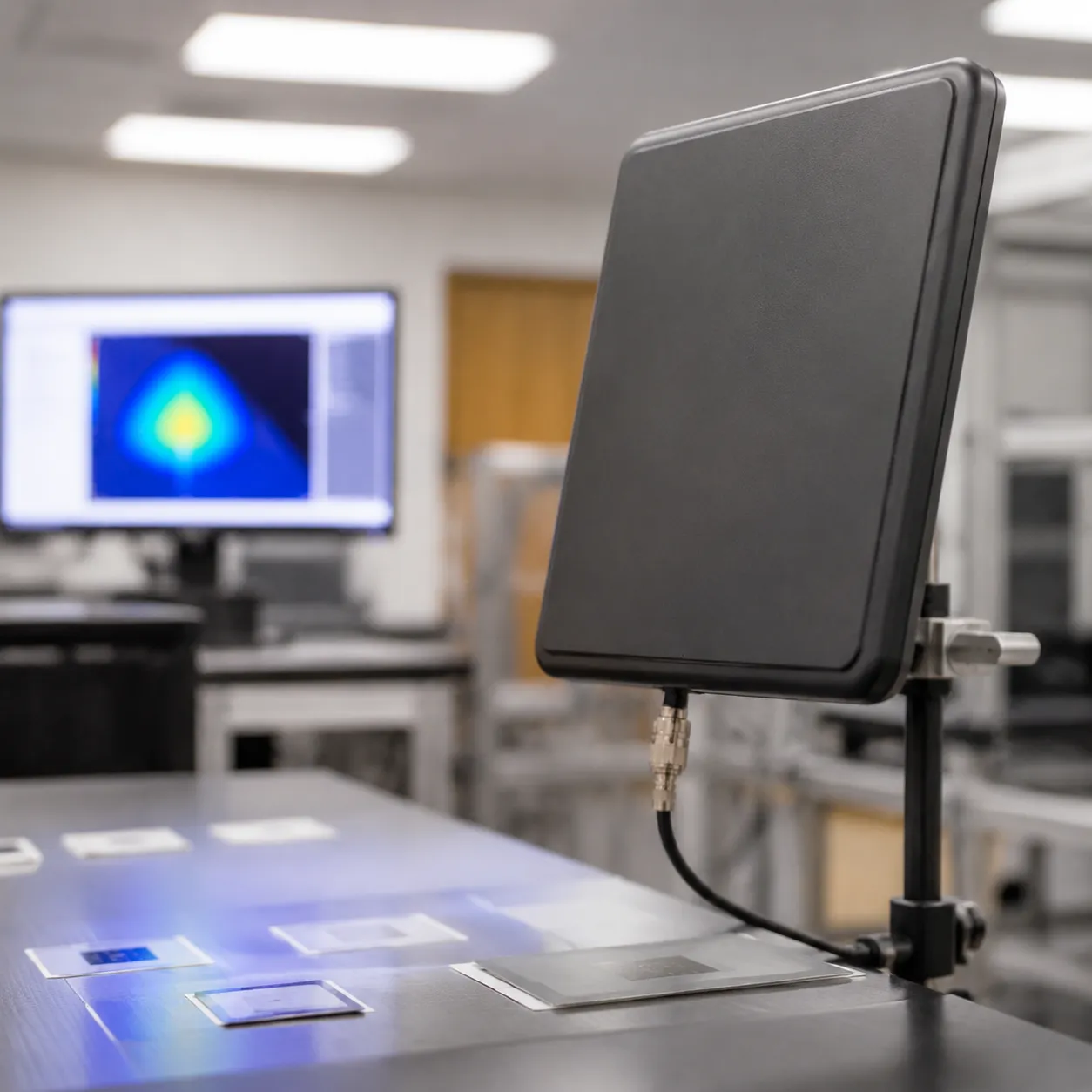
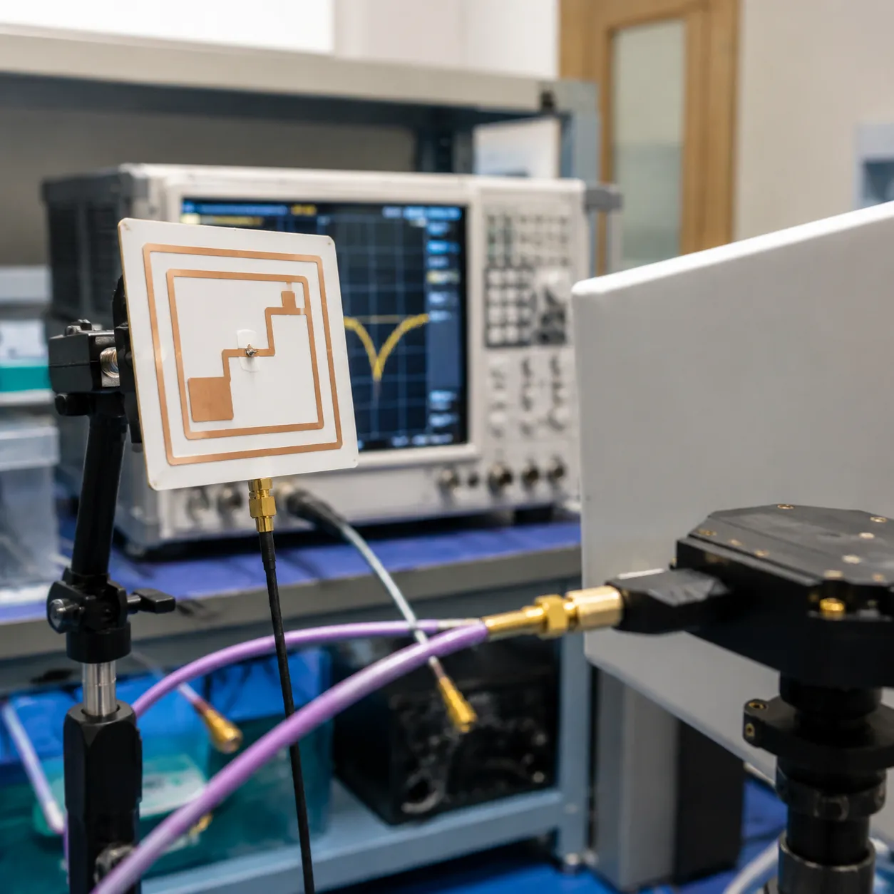
Before we commit to mass production, we eliminate the guesswork. We simulate and test the return loss and radiation pattern of the tag design using specialized RF modeling software.
- Return Loss Testing: We measure how much RF energy is reflected back rather than absorbed, ensuring a perfect conjugate matching between the chip and the antenna.
- Range Validation: We test the actual transmission distance and detection range against standard readers to ensure the tag meets your deployment needs.
- Material Tuning: We adjust the layout to compensate for the specific dielectric properties of your target surfaces, preventing detuning before the first production run ever starts.
Eliminating UHF RFID Tag Antenna Gain Variance in High-Volume Runs
When manufacturing millions of RFID tags, consistency is everything. Even a microscopic deviation in the antenna layout can shift the resonant frequency, drop your signal strength, and alter the UHF RFID tag antenna gain. In high-volume environments like automated US warehouses or retail supply chains, these minor inconsistencies lead to a major headache: missed reads during bulk scanning.
Stable uhf rfid tag data relies entirely on strict physical precision. If the antenna gain drops even slightly due to a manufacturing defect, the tag won't harvest enough energy to power its integrated circuit (IC), instantly crushing your expected read range.
Our Automated QA Protocols
To prevent gain inconsistency, we implement rigorous, automated quality control directly on our production lines:
- Raw Substrate Inspection: We continuously audit PET films, conductive inks, and copper layers to ensure uniform thickness and permittivity before assembly.
- Microscopic Alignment Checks: Our automated vision systems instantly catch sub-millimeter shifts in meander line dipoles and flip-chip placements.
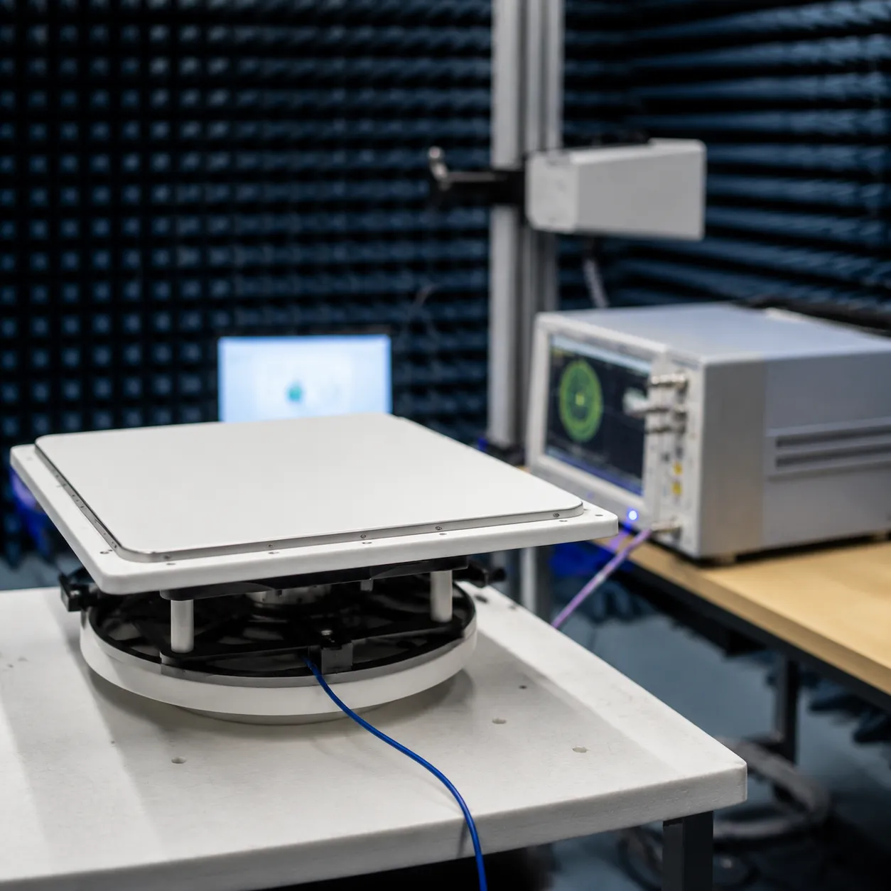
- 100% Electronic Validation: Every single inlay undergoes high-speed electronic testing to verify its actual detection range and ensure the radiation pattern matches our design benchmarks.
Globally Certified Compliance
We don't guess at performance; we verify it. Our manufacturing facilities maintain strict adherence to international standards to guarantee that every batch delivers a predictable transmission distance and reliable signal integrity.
| Certification | What It Guarantees For Your Deployment |
|---|---|
| ISO 9001:2015 | Strict quality management and repeatable, flaw-free manufacturing processes. |
| CE Certification | Full compliance with European safety, health, and environmental requirements. |
| FCC Standards | Perfect alignment with US radio frequency regulations and Effective Isotropic Radiated Power (EIRP) limits. |
By eliminating variance on our factory floor, we ensure that your specific uhf rfid tag size constraints never compromise the real-world performance of your tracking systems.
FAQs: UHF RFID Tag Antenna Gain
How does tag antenna gain affect the read range?
UHF RFID tag antenna gain directly determines how far away a reader can detect a tag. Since a passive antenna relies entirely on energy harvesting from the reader's signal to power its integrated circuit (IC), higher gain means the tag captures and reflects RF energy more efficiently.
| Tag Antenna Gain | Signal Strength | Read Range | Best Use Case |
|---|---|---|---|
| High Gain | Stronger reflection | Long detection range | Open spaces, supply chain pallets |
| Low Gain | Weaker reflection | Short detection range | Item-level retail, dense packaging |
What is the difference between linear and circular polarization in tag performance?
Polarization matches how the reader and the tag talk to each other. It heavily impacts the transmission distance and overall signal strength:
- Linear Polarization: Offers a longer transmission distance but requires the tag and reader antennas to align perfectly. If the orientation is off, you lose signal strength.
- Circular Polarization: Splits the reader signal into a rotating wave. It reduces maximum read range slightly but reads tags reliably at almost any angle or orientation.
Can you customize a UHF RFID tag antenna for metallic surfaces?
Yes, we design and manufacture these daily. Metal surfaces reflect RF energy and short out standard dipoles, completely detuning the tag. To fix this, we engineer custom on-metal tags using specialized substrate materials and advanced geometries. These custom designs insulate the tag and optimize the uhf rfid tag antenna gain, ensuring a reliable read range even in harsh industrial environments.