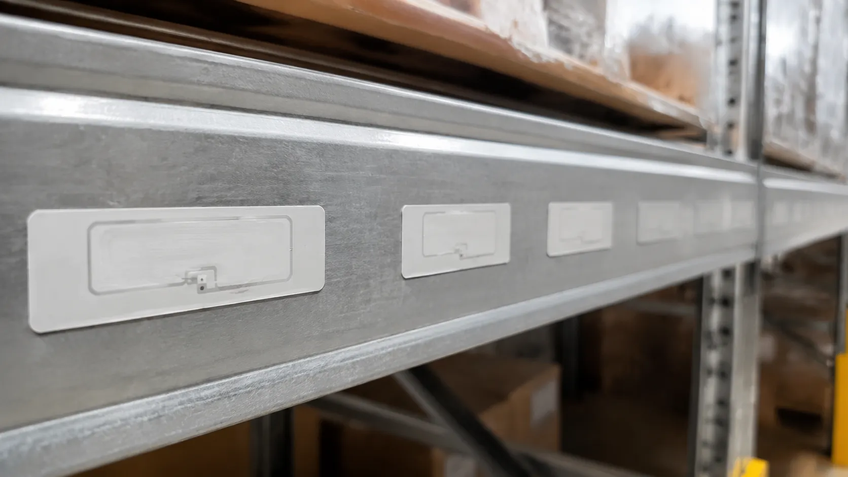

UHF RFID tag minimum spacing guidelines industry standard refers to field-tested center-to-center gaps—not one global mandate—for RAIN RFID layouts in the 860–960 MHz frequency band.
- Guidelines vs standards: The EPC Gen2 standard defines air-interface behavior; spacing tables are engineering practice from substrate and reader testing.
- Universal floor: ~0.5 in (12.7 mm) center-to-center before near-field detuning and tag interference dominate.
- Substrate sets gaps: Free air, apparel, liquid cases, and metallic surfaces each shift the matrix.
Below: mutual coupling physics, the spacing matrix, mechanical workarounds, and FAQ troubleshooting.
UHF RFID Tag Spacing: Physics & Mutual Coupling
Mutual Coupling: How Adjacent Antennas Detune the 860–960 MHz Frequency Band
When two passive RFID inlays sit next to each other, their dipole antennas interact through mutual coupling. This electromagnetic interaction fundamentally alters their resonance.
- Frequency Detuning: The presence of a neighboring antenna shifts the tag’s operating frequency outside the standard 860–960 MHz frequency band.
- Impedance Mismatch: As the tag detunes, energy transfer between the microchip (such as Impinj® or Alien® chips) and the antenna becomes inefficient.
- Energy Loss: The tag fails to gather enough RF energy from the RFID reader antenna to power up and backscatter its signal.
The "0.5-Inch Red Line": The Near-Field Boundary Restriction Explained
To avoid severe tag interference, maintain a strict physical gap between labels. The 0.5-inch (12.7 mm) center-to-center spacing limit serves as a baseline physical threshold in standard open-air applications.
- Near-Field Distortion: Spacing tags closer than 0.5 inches puts them inside each other's reactive near-field zone, triggering intense antenna coupling.
- Severe Read Range Degradation: Crossing this boundary can shrink your overall read range by up to 80%.
- Shadowing Effects: The front tag absorbs or reflects the RF energy, leaving adjacent tags completely unpowered.
Signal Attenuation vs. Anti-Collision Protocols
A common misconception is that software can fix physical signal loss. While GS1/EPC Gen2 standard anti-collision algorithms (like slotted Aloha) excel at organizing responses from hundreds of tags at once, they cannot overcome physical signal degradation.
| Feature / Factor | EPC Gen2 Anti-Collision Protocol | Mutual Coupling Detuning |
|---|---|---|
| Primary Function | Resolves data transmission collisions | Physical alteration of tag resonance |
| System Impact | Manages channel access timing | Prevents the chip from powering on |
| Software Solution? | Yes (manages tag inventory rounds) | No (physics hardware limitation) |
If adjacent tags suffer from mutual detuning, they never absorb enough power to wake up. RAIN RFID software protocols cannot read a tag that lacks the physical energy to respond. Correct physical layout remains the first line of defense. Regional channel spacing rules also cap reader power and band plans—layout gaps still govern tag-to-tag antenna coupling.
UHF RFID Tag Minimum Spacing Guidelines: Industry Standard Matrix
In RAIN RFID deployments, substrate material is the single biggest variable that dictates your tag layout. Standard dry inlays might perform beautifully in open air, but once you apply them to cardboard, liquids, or metals, the physical dielectric properties shift. This shift detunes the tag's antenna away from the optimum 860–960 MHz frequency band, causing severe read range degradation.
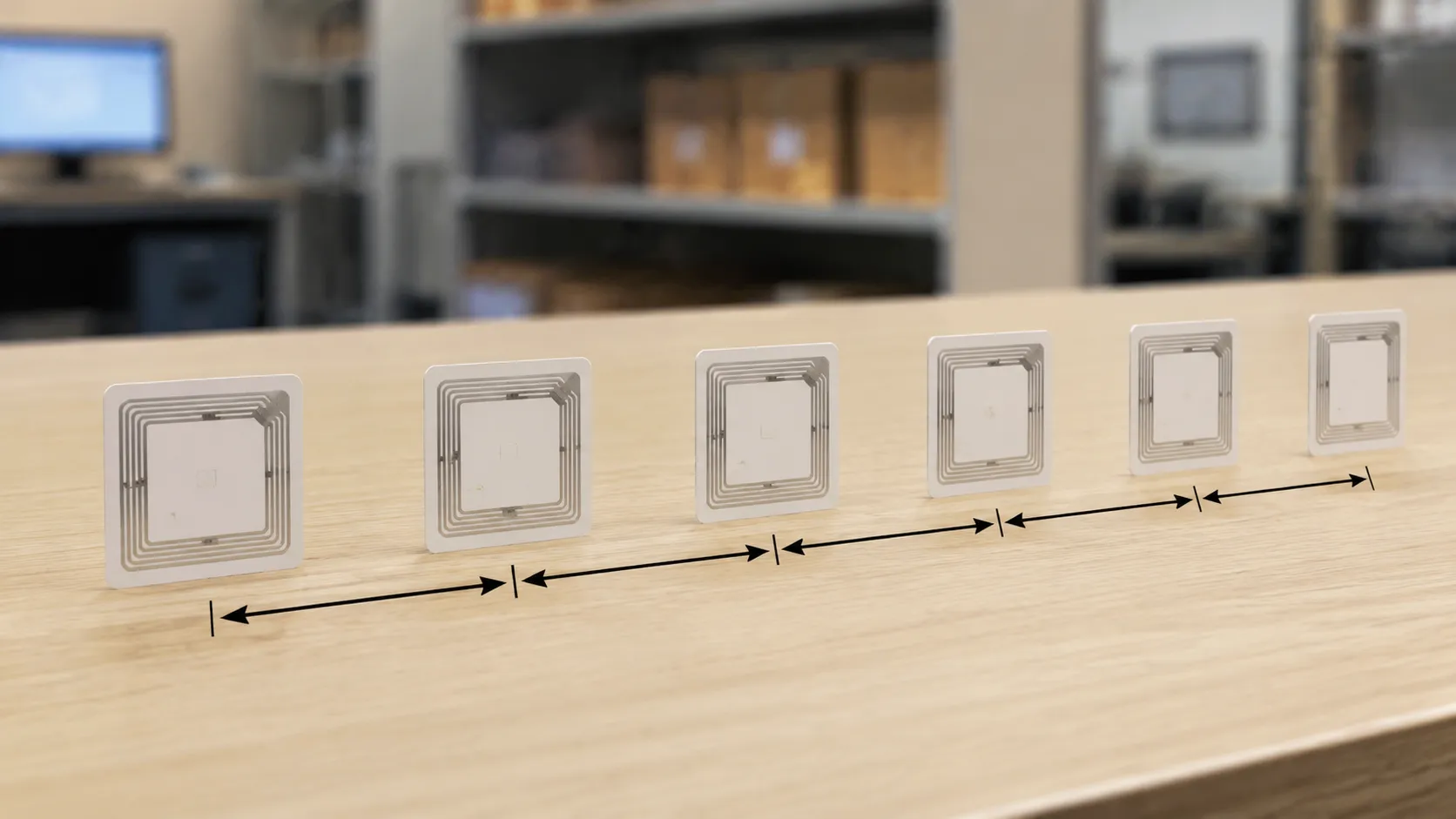
To prevent tag interference and maintain the integrity of your EPC Gen2 standard systems, this baseline reference matrix summarizes common field gaps. Compare minimum spacing between UHF RFID tags to avoid interference for reader-side layout rules.
Recommended Minimum Center-to-Center Spacing
The table below outlines our engineering recommendations for uhf rfid tags minimum center to center spacing based on the target substrate and application environment:
| Application & Material | Recommended Minimum Center-to-Center Spacing | Primary Substrate Interference & Impact |
|---|---|---|
| Free Space / Open Air | 1.0 inch (25.4 mm) | Zero substrate interference; baseline physical gap to prevent mutual coupling. |
| Retail & Apparel (Cardboard/Paper) | 1.5 inches (38.1 mm) | Mild detuning from dense cardboard packaging; easily managed with standard RFID reader calibration. |
| Logistics & Liquid-Filled Cases | 3.0 inches (76.2 mm) | Severe RF absorption from water; wider spacing is required to prevent massive signal degradation. |
| On-Metal Surfaces (Specialized Tags) | 2.0 inches (50.8 mm) | Metallic surfaces reflect RF waves; requires specialized on-metal RFID tags to prevent complete detuning. |
| Vehicle Windshields (Access Control) | 4.0 inches (101.6 mm) | Glass and metallic tinting compress the RF field; requires maximum physical separation for high-speed reads. |
How Substrates Compress Your Spacing Limits
When passive tags are applied to dense or conductive materials, the physical environment alters how the RFID reader antenna interacts with the inlay.
- Cardboard and Packaging: While dry cardboard is relatively RF-friendly, stacked or tightly packed boxes compress the air gap between layers. This compression triggers mutual coupling, requiring you to increase the physical gap between tags to prevent them from detuning each other.
- Water and Liquids: Water absorbs UHF energy. If tags are placed too close to liquid-filled containers or to one another on a liquid-heavy pallet, the signal simply dies. Expanding your spacing to at least 3 inches keeps the tags outside of each other’s dampened boundary fields.
- Metallic Surfaces: Metal is highly conductive and reflects RF energy, which completely shorts out standard passive tags. Even when using specialized on-metal RFID tags, keeping a strict minimum center-to-center physical gap of 2 inches is critical to prevent the metal substrate from distorting the reader's signal path.
3 Mechanical Workarounds for Tight Tag Footprints
When layout constraints make ideal gaps impossible, three field-proven mechanical workarounds reduce signal degradation while preserving read range.
1. Tag Orientation Alignment (90° and 45° Offsets)

When passive tags are placed too close together, their antennas couple and detune. Changing tag orientation breaks coupling—see installing UHF RFID tags for consistent placement in the field.
- 90-Degree Rotation: Alternating adjacent tags between horizontal and vertical orientations minimizes mutual coupling.
- 45-Degree Angular Offset: If a grid layout is required, angling the tags at 45 degrees helps maintain independent polarization fields.
- Polarization Matching: Align offset tags with a circularly polarized RFID reader antenna for reliable wake-up without losing read efficiency.
2. Reader Antenna Tuning & Transmit Power Calibration
Sometimes the fix is not on the asset, but how the RFID reader is configured. Over-powering a tight cluster of tags causes massive tag interference.
- Reduce Transmit Power (dBm): Lowering the reader's power shrinks the RF zone, targeting only the closest tag and preventing adjacent tags from responding simultaneously.
- Narrow-Beam Antennas: Swap wide-angle antennas for highly focused, near-field patch antennas to isolate closely spaced tags.
- Software Session Tuning: Leverage EPC Gen2 standard sessions (like Session 2 or 3) to keep clustered tags quiet once they are read, preventing them from blocking neighboring signals.
3. Custom Inlay Geometry and Dielectric Spacers
When standard labels fail due to tight spacing or challenging backings, custom physical materials are the best defense.
- Thicker Dielectric Spacers: Adding a synthetic foam spacer (1mm to 3mm) lifts the tag antenna away from neighboring substrates, neutralizing close-range interference.
- Specialized Tag Inlays: Narrow loop inlays help when label size guidelines on printers (often ~0.5–0.98 in minimum width) still allow adequate physical gap between adjacent antennas.
- On-Metal Isolation: When applying tags near metallic surfaces or in dense grids, specialized on-metal RFID tags utilize built-in shielding layers to prevent detuning.
UHF RFID Minimum Spacing Guidelines: FAQs
Deployment teams often ask these questions trying to squeeze maximum performance out of tight layouts. When pushing the limits of the uhf rfid tag minimum spacing guidelines industry standard, here is how the physics play out in real-world environments.
Can I overlap passive RFID tags?
No. Overlapping passive tags is the fastest way to kill your read rates.
When two UHF RFID tags overlap or touch, their antennas physically combine to form a single, detuned electrical conductor. This destroys their ability to resonate within the designated frequency band (860–960 MHz).
The Detuning Effect: Even if the chips don't physically touch, the overlapping metal patterns create extreme mutual coupling detuning. This shifts their resonant frequency completely out of the reader’s range, leaving both tags entirely unreadable.
The Golden Rule: Always maintain a physical gap of at least 0.5 inches (12.7 mm) to prevent severe read range degradation.
How does reader polarization impact minimal spacing?
The design of your RFID reader antenna directly dictates how closely you can pack your tags.
| Antenna Polarization | Best For | Spacing Impact |
|---|---|---|
| Circular Polarization | Mixed or random tag orientations | Requires wider spacing. Because circular antennas broadcast RF waves in a rotating, helical pattern, they are highly prone to activating multiple adjacent tags simultaneously. This increases the risk of tag interference in tight configurations. |
| Linear Polarization | Controlled, aligned tag travel | Allows tighter spacing. Linear antennas focus all their electromagnetic energy along a single vertical or horizontal plane. If you align your tags perfectly with this plane, you can tighten the spacing because the field is narrower and highly directional. |
When should I switch to a specialized JN RFID on-metal tag?
Standard passive paper labels require an air gap to function. When applied directly to metallic surfaces, the metal acts as a ground plane, reflecting the RF energy and completely shorting out the tag's antenna.
Switch to on-metal UHF RFID tags when any of the following apply:
- Direct Metal Mounting: The asset is made of raw steel, aluminum, or foil-lined packaging.
- Extreme Signal Loss: Standard labels show immediate signal degradation or zero read range when placed within 1 inch of a metal boundary.
- Tight Footprints on Metallic Assets: You need to track high-value metal tools, server blades, or automotive parts where physical spacing is constrained. On-metal inlays use ceramic or FR4 dielectric spacers to isolate the antenna, allowing you to bypass standard free-space spacing restrictions altogether.