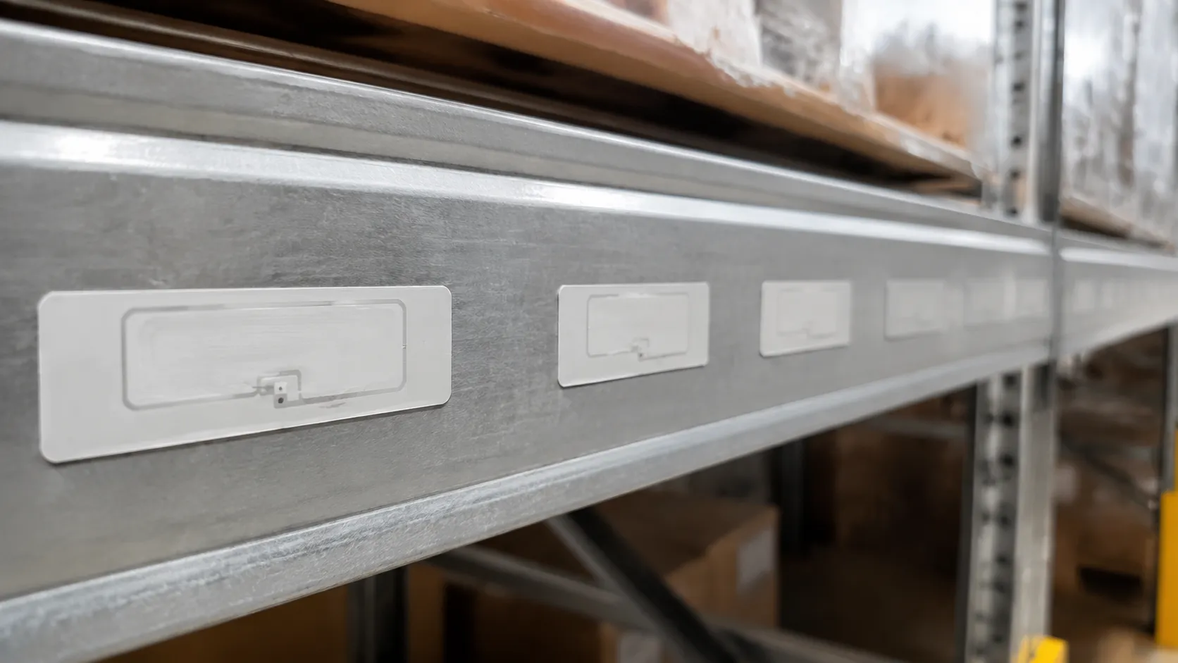

Setting uhf rfid tag to tag interference minimum spacing starts with substrate and packing density—not reader firmware alone. Use this snapshot before you lock a high-density layout.
| Application / Substrate | Minimum spacing |
|---|---|
| Apparel & hanging tags | 1.0–1.5 in (2.5–3.8 cm) |
| Corrugated cartons | 1.5–2.0 in (3.8–5.0 cm) |
| On-metal tags | 2.0–3.0 in (5.0–7.6 cm) |
| Near-field danger zone | <0.5 in (<1.2 cm) — severe detuning |
Below we explain uhf rfid tag to tag minimum spacing interference, mutual coupling, tag-to-tag collision vs detuning, and field fixes when ideal gaps are impossible.
UHF RFID Tag to Tag Interference Minimum Spacing: The Golden Rules
One question dominates field testing for “How close can we pack these tags before they stop reading?”
When passive tag antennas sit too close, they magnetically and electrically couple, causing severe detuning. To ensure your deployment succeeds, we have established clear boundary limits for uhf rfid tag to tag interference minimum spacing.
The Free-Air Standard: The 1.0 to 2.0-Inch Safety Baseline
For standard dry-label applications in open air, keep a minimum distance of 1.0 to 2.0 inches (2.5 to 5.0 cm) between tags.
- Why this range? At this distance, the electromagnetic fields of adjacent passive dipole antennas do not significantly overlap.
- The Result: The tag maintains its designed impedance, allowing the reader's interrogator antenna to power up the IC and capture the backscattered signal without read range degradation.
The Near-Field Danger Zone: Under 0.5 Inches (1.2 cm)
Once tag spacing drops below the 0.5-inch (1.2 cm) threshold[3], you enter the near field danger zone.
- Severe Detuning: The tags begin to share electromagnetic energy (mutual coupling), which shifts their resonant frequency away from the standard global UHF band (860–960 MHz).
- Signal Attenuation: The tag ICs fail to gather enough energy to turn on (P_{turn-on} increases significantly), causing immediate, severe read range loss or complete dead zones in your interrogation area.
At-a-Glance Minimum Spacing Reference Table
The substrate material holding the tag heavily influences electromagnetic coupling. Use this quick deployment reference to set your physical layout baselines:
| Application / Substrate | Recommended Minimum Spacing | Interference Risk Level Below Minimum | Key Field Behavior |
|---|---|---|---|
| Apparel & Hanging Tags | 1.0" – 1.5" (2.5 – 3.8 cm) | Medium | Rapid detuning when stacked or folded directly on top of each other. |
| Corrugated Cardboard | 1.5" – 2.0" (3.8 – 5.0 cm) | Low to Medium | Safe margin for dense pallet loading and case-pack scanning. |
| On-Metal RFID Tags | 2.0" – 3.0" (5.0 – 7.6 cm) | High | Metal surfaces amplify parasitic capacitance; tags require maximum separation. |
| Vehicle Access Control | 3.0"+ (7.6 cm+) | High | Windshield glass and high-power reader beams require wide physical gaps to prevent cross-reads. |
Mutual Coupling & Detuning: Why UHF Tags Interfere
When you pack passive UHF RFID tags too close together, they stop acting like independent transponders and start acting like a single, disorganized system. To keep your read rates high, you need to understand the physical forces driving uhf rfid tag to tag interference minimum spacing limits.
Here is what happens to your RF signal when tags crowd each other's personal space.
Understanding Mutual Coupling in Passive UHF RFID Tags
Passive UHF RFID tags rely on backscatter coupling to communicate with the interrogator antenna. When two dipole antennas are placed side-by-side, they share an electromagnetic field. This mutual coupling[1] causes the tags to steal energy from one another. Instead of sending clean data back to your reader, the adjacent tags absorb and scatter each other's signals, leading to severe read range degradation.
The Detuning Phenomenon
Every standard dipole antenna on a passive tag is tuned to a resonant frequency within the global UHF band of 860–960 MHz[2].
The Shift: When another tag enters the immediate electromagnetic field, it shifts this resonant frequency.
The Consequence: The tag detunes, shifting its operating frequency outside the range of your interrogator antenna.
The Result: The reader can no longer "see" the tag, even if it is well within the nominal detection range.
Impedance Mismatching and Turn-on Power Loss
For a tag to wake up, the impedance of its antenna must perfectly match the chip's input impedance. High-density tag deployment disrupts this delicate balance, causing an impedance mismatch.
Without a clean impedance match, the tag IC cannot harvest enough energy from the reader's RF field. This spikes the required turn-on power (P_{turn-on}), meaning the tag requires significantly more power just to boot up and reply.
Power Margin Reduction: The Real-World Data
In our testing lab, we consistently measure how spacing impacts the power margin—the extra energy a tag has over its absolute minimum response threshold.
| Tag Spacing (Distance) | Average Power Margin Loss | Impact on Read Range |
|---|---|---|
| Greater than 5.0 cm (2.0 in) | 0% (Baseline Performance) | Maximum rated detection range |
| 3.0 cm to 5.0 cm | 10% to 15% Loss | Minor range drop; acceptable for most bins |
| 2.0 cm (0.8 in) | Up to 40% Loss | High risk of missed reads in rapid transit |
| Under 1.2 cm (0.5 in)[3] | Severe Signal Attenuation | Complete tag blackout; failure to power up |

Under 2.0 cm, you face a steep drop-off in performance. High-density retail, warehousing, and asset tracking layouts should keep tags outside this interrogation zone attenuation band for reliable read range. See also minimum spacing between UHF RFID tags for reader-side layout rules.
Tag Detuning vs Tag-to-Tag Collision in Gen2 UHF
When troubleshooting a dense tag deployment, we often see field teams confuse physical tag interference with protocol collisions. If your tags are dropping off the reader, you have to know whether you are fighting a physical hardware limit or a software traffic jam.
Physical Detuning (The Hardware Issue)
When passive tags are packed tighter than the recommended uhf rfid tag to tag interference minimum spacing, they experience mutual coupling. This is a pure electromagnetic hardware problem where adjacent dipole antennas share energy and alter each other's electrical properties.
The Result: The resonant frequency of the antenna shifts away from the standard global UHF band (860–960 MHz).
What Happens: This detuning causes a severe impedance mismatch. The tag's turn-on power requirement spikes, meaning the interrogator antenna physically cannot transmit enough energy to wake the microchip up.
The Fix: This cannot be fixed with software. It requires physical deployment adjustments like staggering, increasing spacing, or altering the tag orientation.
Tag-to-Tag Collision (The Protocol Issue)
In contrast, tag-to-tag collision is a software-level communication bottleneck.
The Result: The passive tags have plenty of power, wake up perfectly, and attempt to speak.
What Happens: Multiple tags try to backscatter their signal to the reader at the exact same millisecond, scrambling the RF transmission.
The Fix: This is handled automatically at the firmware level. The EPC Class 1 Gen 2 protocol (Gen2 tag air interface)[2] uses a Slotted Aloha algorithm (the Q-system) to systematically quiet down responding tags and read them one by one.
Quick Comparison: Hardware vs. Protocol Interference
| Feature | Mutual Coupling (Detuning) | Tag-to-Tag Collision |
|---|---|---|
| Root Cause | Physical proximity (under minimum spacing) | Simultaneous data transmission |
| System Level | Electromagnetic Hardware | Firmware / Air Interface Protocol |
| Power State | Tag IC fails to turn on due to high power threshold | Tag IC powers up successfully |
| How to Resolve | Increase physical spacing, adjust tag geometry | Handled automatically via EPC Gen2 Slotted Aloha[2] |
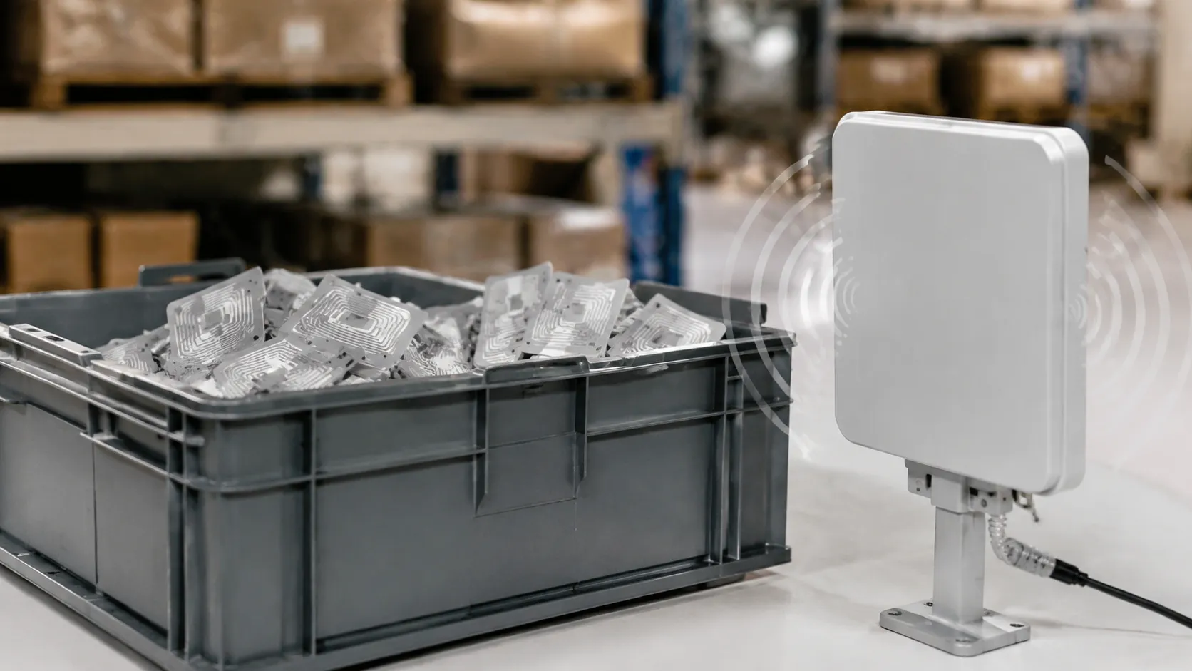
By keeping these two issues distinct, we can quickly isolate the exact bottleneck in high-density setups without wasting time tweaking software settings to fix a physical spacing issue.
Spacing Fixes: Orientation, Polarization & Near-Field Tags
Tight packaging often breaks the ideal uhf rfid tag to tag interference minimum spacing. When physical space limits you, we use these proven engineering and deployment strategies to bypass the physics of mutual coupling and keep your read rates at 100%.

Smarter Tag Layouts: Geometrical Offsets
If you have to pack items tightly, do not align the tag antennas in a perfect parallel line. This layout maximizes electromagnetic coupling and kills your read range.
- Stagger the Placement: Offset adjacent tags diagonally so dipole antennas do not overlap—tag orientation and staggering reduce electromagnetic coupling.
- The 96-Degree Rule: Rotate every second tag by roughly 90 to 96 degrees. By breaking the parallel alignment of the dipole antennas, you drastically reduce energy sharing and drop detuning to near zero.
Polarization Matching and DRM Configuration
Your reader antenna setup plays a massive role in how well tightly spaced tags perform.
- Circular Polarization: We generally recommend circular polarization on reader antennas for high-density environments. They tolerate varied tag orientations much better than linear antennas, which require perfect alignment.
- Enable Dense Reader Mode (DRM): In high-density setups, configure your RFID readers to DRM. This tightens the reader's spectral masks and optimizes channel spacing, preventing the reader itself from overpowering closely grouped tags.
Going Near-Field for Micro-Spacing
When layout requires uhf rfid tag-to-tag interference minimum spacing under 0.5 in, far-field tags fail—compare minimum distance between UHF RFID tags for reader-side separation.
In these micro-spacing environments, we transition clients to near-field UHF loop antennas and near-field tags. Because near-field communication relies on magnetic fields rather than propagating radio waves, the tags do not suffer from the same severe mutual coupling or detuning issues, allowing you to scan highly congested items with pinpoint accuracy.
OEM Inlay Tuning for High-Density Tag Layouts
When you are deploying tags in ultra-dense environments, off-the-shelf options just don't cut it. Standard tags are tuned for isolated environments, meaning they fail when packed tightly together. Custom manufacturing protocols to actively combat uhf rfid tag to tag interference minimum spacing issues right at the factory level.
Here is exactly how we customize and build passive UHF RFID tags to handle tight spacing without dropouts.
Custom Antenna Substrate Profiling
Standard tag antennas suffer from severe antenna detuning and impedance mismatch when stacked closely. To fix this, we customize the antenna design and substrate material to match your specific application.
- Impedance Stabilization: We modify the loop inductance and dipole antenna geometry to pre-compensate for the shift caused by nearby tags.
- Substrate Tuning: By adjusting the dielectric properties of the tag carrier, we ensure the antenna remains stable even when mutual coupling tries to pull it off-frequency.
- Minimized Footprints: We design ultra-thin, highly directive antenna profiles that naturally limit the reach of their electromagnetic fields, effectively shrinking the required uhf rfid tag-to-tag interference minimum spacing.
High-Sensitivity Silicon Integration
When physical spacing drops below the safe threshold, signal attenuation is inevitable. We bypass this loss by integrating top-tier, high-sensitivity integrated circuits (ICs) into our tags.
- Low Turn-on Power (P_turn-on): We utilize next-generation silicon chips that require exceptionally low power to wake up.
- Bypassing Attenuation: Even if mutual coupling drains a portion of the incoming energy, these highly sensitive ICs still power up and backscatter successfully.
- No Read Range Degradation: By lowering the required power threshold, we maintain a strong, consistent read range even in high-density environments where other tags go completely dark.
100% Electronic Pre-Shipment QA Validation
We don't guess how our tags will perform under pressure—we test every single one. Zero-failure deployments depend on rigorous quality control at the inlay level.
- Dynamic Write & Read Threshold Testing: Every production run goes through automated RF testing to measure the precise turn-on power (P_turn-on) and backscatter strength.
- High-Density Simulation: We sample-test our production lots in clustered configurations to verify they meet strict performance baselines under severe mutual coupling scenarios.
- Guaranteed Yield: You receive tags with verified, stable write thresholds, ensuring fast commissioning and reliable reads straight out of the box.